Yaskawa RC5 Converter User Manual
Page 57
YASKAWA ELECTRIC TOEP C710656 01C YASKAWA - RC5 Instruction Manual
57
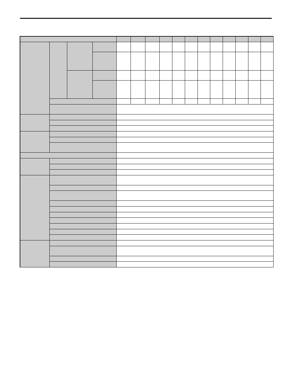
Table 7.2 400 V Class Specifications
Note: Use a power regenerative unit with larger output capacity if the imbalance rate between phases exceeds 2%.
Note: <1> Imbalance rate between phases can be calculated using the following formula (Conforming to IEC1800-3). Imbalance rate between phases [%] = Three-phase
average voltage divided by (Max. voltage - Min. voltage) x 67.
Model CIMR-R5U
43P7
45P5
47P5
4011
4015
4018
4022
4030
4037
4045
4055
4075
Rating
Rated
Capacity
Heavy Duty
(See Note 2)
HP (kW)
3
(2.2)
5
(3.7)
7.5
(5.5)
10
(7.5)
15
(11)
20
(15)
25
(18.5)
30
(22)
40
(30)
50
(37)
60
(45)
75
(55)
Rated
Current on
Input Side
(100% Cont.)
4
6
8
12
16
20
24
32
40
48
60
80
Standard
Duty
(See Note 2)
HP (kW)
5
(3.7)
7.5
(5.5)
10
(7.5)
15
(11)
20
(15)
25
(18.5)
30
(22)
40
(30)
50
(37)
60
(45)
75
(55)
100
(75)
Rated
Current on
Input Side
(100%, 60s)
5
7.5
10
15
20
25
30
40
50
60
75
100
Rated DC Current A
6
9
13
19
26
32
37
51
64
77
96
128
Regenerative Torque
Heavy Duty: 100% cont., 125% for 60 s (25% ED), 187.5% for 30 s, max. torque < 250%
Standard Duty: 80% cont., 100% for 60s (25% ED), 150% for 30s, max. torque < 200%
Input Power
Supply
Voltage Frequency
380 to 460 VAC 50/60 Hz,
Allowable Voltage Fluctuation
+ 10 to - 15% (Imbalance rate between phases: within 2%) <1>
Allowable Frequency Fluctuation
± 3 Hz (3 phase rotation)
Control
Characteristics
Control Method
120° current conduction
Input Power Factor
0.9 or more (Rated current)
Overload Capacity
Standard Duty: 150% for 30 seconds
Heavy Duty: 187.5% for 30 seconds
Operation Input
External terminals
Status Output
Fault
1C contact output
Running, READY Signal
Photocoupler output
Analog Output
Analog output: 1 point can be selected (current monitor)
Protective
Function
Instantaneous Overcurrent
Standard Duty: Stops at approx. 200% of the current on power side
Heavy Duty: Stops at approx. 250% of the current on power side
Blown Fuse
Motor stops by blown fuse.
Overload
Standard Duty: Stops after 30 seconds at 150% of rated current.
Heavy Duty: Stops after 30 seconds at 187.5% of rated current.
Undervoltage (DC Voltage)
Stops at approx. 380 VDC or less.
Undervoltage (Power Side Voltage)
Stops at approx. 300 VAC or less.
Overload
Stops at approx. 800 VDC or less.
Fin Overheat
Protected by thermistor
Power Supply Open Phase
Stops at power supply open phase detection.
Power Frequency Error
Stops by fluctuation more than ± 3 Hz of rated input frequency.
Power Charge Indication
Indicated until main output voltage is approx. 50 V or less.
Environmental
Conditions
Location
Indoor (Protected from corrosive gases and dust)
Ambient Temperature
- 10°C to + 40°C (Closed wall–mounted)
- 10°C to + 45°C (Open chassis type)
Humidity
90% RH or less (non–condensing)
Vibration
9.8 m/s
2
(1G) less than 20 Hz, up to 1.96 m/s
2
(0.2G) at 20 to 50 Hz