PLANET IGS-10020HPT User Manual
Page 146
User’s Manual of IGS-10020PT / IGS-10020HPT
146
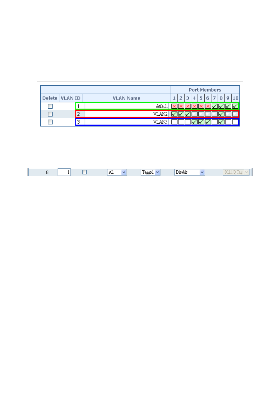
1. Specify Port-8 to be the 802.1Q VLAN Trunk port.
2. Assign Port-8 to both VLAN 2 and VLAN 3 at the VLAN Member configuration page.
3. Define a VLAN 1 as a “Public Area” that overlaps with both VLAN 2 members and VLAN 3 members.
4. Assign the VLAN Trunk Port to be the member of each VLAN, which wants to be aggregated. For this sample, assign
Port-8 to be a VLAN 2 and VLAN 3 member port. The screen in
Figure 4-6-12
appears.
Figure 4-6-12: VLAN overlap port setting & VLAN 1 – The Public Area Member Assign
5. Specify Port-8 to be the 802.1Q VLAN Trunk port, and the Trunking port must be a Tagged port while egress. The Port-8
configuration is shown in the following screen in
Figure 4-6-1
3
.
Figure 4-6-13: The configuration of VLAN Trunk Port
That is, although the VLAN 2 members: Port-1 to Port-3 and VLAN 3 members: Port-4 to Port-6 also belong to VLAN 1. But with
different PVID settings, packets from VLAN 2 or VLAN 3 are not able to access to the other VLAN.
6. Repeat Steps 1 to 5, set up the VLAN Trunk port at the partner switch and add more VLANs to join the VLAN trunk. Repeat
Steps 1 to 3 to assign the Trunk port to the VLANs.