ProSoft Technology MVI46-DNP User Manual
Page 110
MVI46-DNP ♦ SLC Platform
Reference
Master/Slave Communication Module
Page 110 of 143
ProSoft Technology, Inc.
August 23, 2007
TIMING CHART:
Several timing parameters are required for each unit in order to implement the
collision avoidance feature. The parameters are as follows:
Parameter Description
Fixed DCD Idle Delay Time Before
Transmit
This parameter specifies the minimum number of milliseconds to delay
before transmitting a message after recognizing that the DCD line is low.
Random DCD Idle Delay Time Before
Transmit
This parameter determines the random time to be added to the above fixed
delay value above before attempting to transmit a message. The value
specified for the parameter determines the range of random values
(milliseconds) to be used. For example, if a value of 20 is specified, the
random delay time will be from 0 to 20 each time the value is requested.
DCD Time Before Receive
This parameter specifies the number of milliseconds to delay after
recognizing that DCD has been asserted before accepting data. The RTS
on time of the sending unit must be set greater that the time specified here
or else the first part of the data message will be ignored.
RTS On Time
This parameter specifies the number of milliseconds to delay after asserting
the RTS modem control line before sending the data.
RTS Off Time
This parameter specifies the number of milliseconds to delay after the data
has been transmitted before dropping the RTS modem control line.
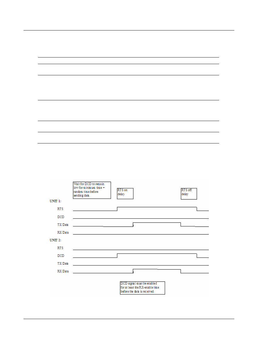
The timing parameters defined above must be set correctly for successful use of
the collision avoidance feature. A timing diagram displaying the data and modem
control lines used with the collision avoidance scheme is shown below. This
example displays the state of the signal lines in transmitting a message from Unit
1 to Unit 2.