Setting jumpers, Module error/status data, Error/status table – ProSoft Technology MVI46-DNP User Manual
Page 93: E 93), Setting, Jumpers, Module, Error/status data
Reference MVI46-DNP
♦ SLC Platform
Master/Slave Communication Module
ProSoft Technology, Inc.
Page 93 of 143
August 23, 2007
5.5 Setting
Jumpers
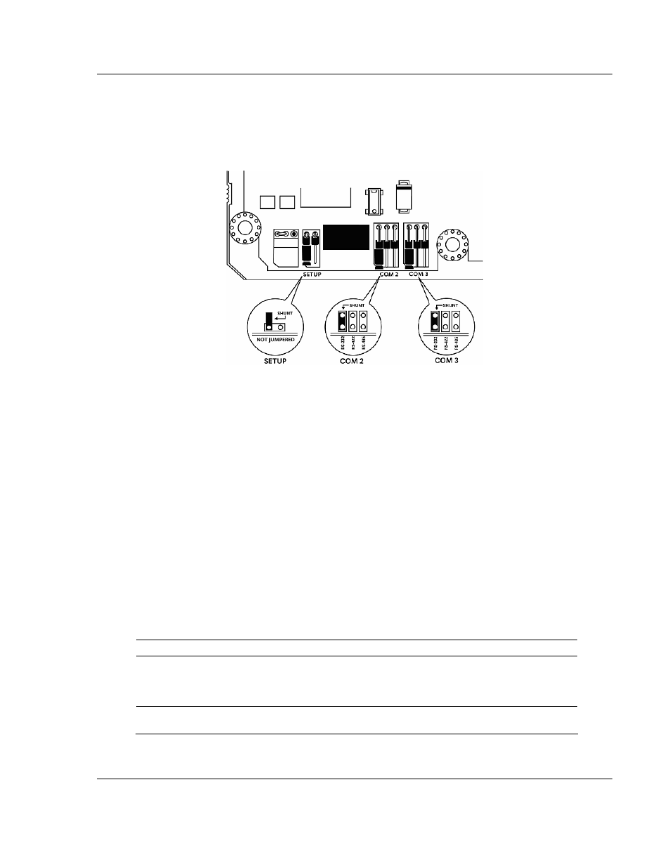
If you use an interface other than RS-232 (default), you must change the jumper
configuration to match the interface. The following illustration shows the MVI46-
DNP jumper configuration:
The Setup Jumper acts as "write protection" for the module's flash memory. In
"write protected" mode, the Setup pins are not connected, and the module's
firmware cannot be overwritten. Do not jumper the Setup pins together unless
you are directed to do so by ProSoft Technical Support.
5.6 Module
Error/Status
Data
The module maintains an Error/Status table. This table of data is available to the
SLC in the M1: file of the module in elements 1536 to 1595. The ladder logic
should be programmed to read this block of data and place the data in a file. This
data can be viewed via the Configuration / Debug Port. You can use the
Error/Status data to determine the "health" of the module. The module
automatically transfers this data to the M1: file at a frequency determined by the
Error Block Delay parameter in the module's configuration.
5.6.1 Error/Status
Table
The data in the SLC file is structured as shown in the following table:
Example Address Word
Data Address Variable Name
Description
N11:0
0
M1: .1536
PLC State
This value represents the current state of the
SLC. The codes returned are as follows:
0=Unknown/Error, 1=Run, 2=Program and
3=Test.
N11:1
1
M1: .1537
DNP Slave Port last
transmitted error code
This value represents the last error code
transmitted to the master by this slave port.