Home tab – MOTU UltraLite-mk5 USB-C Audio/MIDI Interface User Manual
Page 32
C U E M I X 5
32
HOME TAB
3
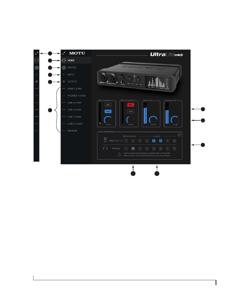
1. Expands and collapses the sidebar.
2. This is the
Home
tab, which provides
quick access to basic settings.
3. The
Device
tab provides basic
hardware settings, such as the
Sample Rate and Clock Source. See
4. The
Input tab
provides settings for
the UltraLite-mk5’s physical inputs,
such as gain levels for the line
inputs. See “Input tab” on page 34.
5. The
Output tab
provides settings for
the UltraLite-mk5’s physical
outputs, such as trim levels for the
line outputs. See “Output tab” on
6. The
Mix
tabs give you access to the
on-board mixing and effects. The
UltraLite-mk5 is a capable 24 x 14
monitor mixer. Each analog output
pair gets its own independent mix
consisting of all inputs, computer
audio and the reverb bus. See “Mix
7. The
Mic/Line/Inst 1-2
panels give
you software control of the settings
for those two front panel inputs. You
can turn on 48V phantom power if
you have a condenser mic connected
to the input, or engage the -20 dB
pad for line level signals. You can
also adjust the preamp gain here.
These are the same as the controls
on the front panel of the unit.
8. Control the unit’s
Main Volume
and
Headphone Volume
here. These are
the same as the controls on the front
panel of the unit.
9. The
Input Monitoring
section lets
you patch the analog inputs directly
to the Main Outs or Headphones.
This is near-zero latency monitoring
because the computer (USB) is not
involved. To hear an input on the
Main Outs, click its button in the top
row; to hear it on the Headphones,
click its button in the bottom row.
If you use this hardware-based
monitoring, be sure to turn off the
input monitoring feature in your
host software. Otherwise, both the
UltraLite-mk5
and
your host
software will send the input signal
to the output and the signal will be
doubled, which can cause phasing
and/or cancellation problems (bad
sound). Consult your software
documentation for details.
10. Here,
Line Inputs 5-6
have been
routed to the main outs. More
specifically, by clicking these
buttons, their faders in the
Main 1-2
Mix
tab have been set to unity
(maximum) gain and mute has been
turned off (if it was on). You can
further adjust the input’s volume or
other settings in its channel strip in
the
Main 1-2 Mix
tab.
11. Here, the
Mic/Line/Inst 2
input has
been routed to the headphones.
However, the button is gray because
the
Mic 2
channel fader has been
lowered (from unity gain) in the
Phones 1-2 Mix
tab. The gray color
alerts you that it is no longer being
monitored at full scale, or that other
channels settings may have been
modified (effects added, channel
muted, etc.)
7
8
2
1
6
9
4
5
10
11