Pilz PSSnet SHL 8T MRP User Manual
Page 101
Redundancy
PSSnet SHL - Web- based Interface
Pilz GmbH & Co. KG, Felix- Wankel Str. 2, 73760 Ostfildern
6.2 Ring/Network coupling
101
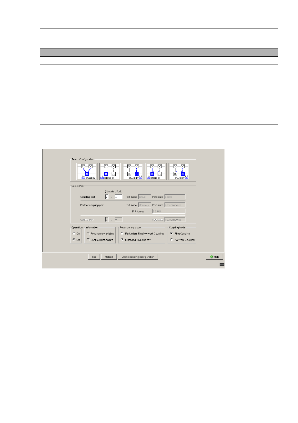
Figure 36: Software configuration of the STAND-BY switch
Depending on the STAND-BY DIP switch position, the dialog displays
those configurations that are not possible in gray. If you want to select one
of these grayed-out configurations, you put the STAND-BY DIP switch on
the Switch into the other position.
One-Switch coupling
Assign the device the DIP switch setting “STAND-BY”, or use the software
configuration to assign the redundancy function to it.
Device with
Choice of main coupling or redundant coupling
DIP switch
On “STAND-BY” DIP switch
DIP switch/software switch
option
According to the option selected
- on “STAND-BY” DIP switch or in the
- Redundancy:Ring/Network Coupling dialog, by making se-
lection in “Select configuration”.
Note: These devices have a DIP switch, with which you can choose
between the software configuration and the DIP switch configura-
tion. If you have set the software configuration, changing the other
DIP switches has no effect.
Software switch
In the Redundancy:Ring/Network Coupling dialog
Table 36: Setting the STAND-BY switch