Pengo TruLink User Manual
Page 12
12
PENGO TruLink Manual
ANCHOR DRIVE TRULINK PIN INSTALLATION
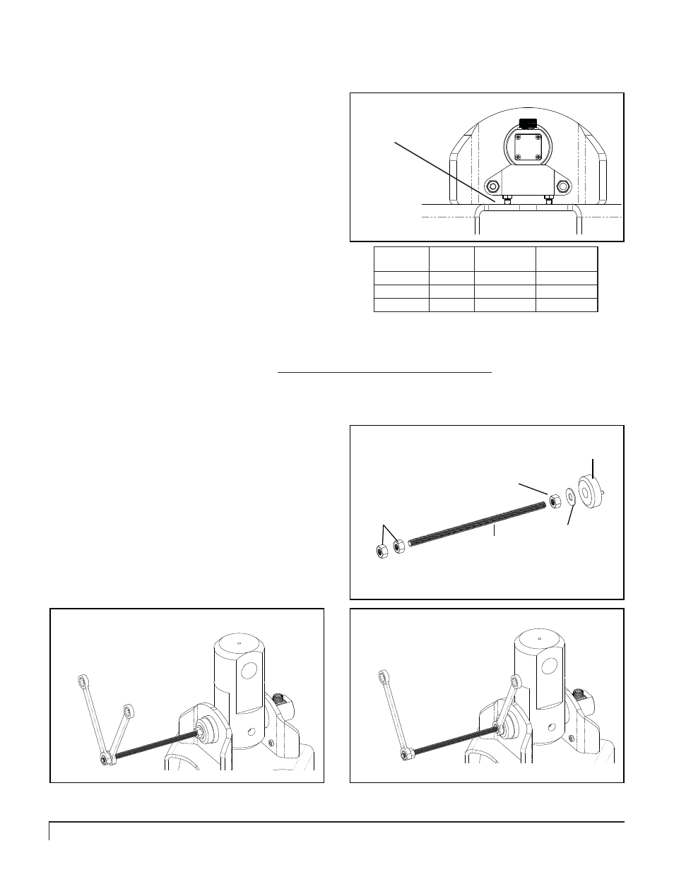
Assemble the Installation Rod as shown in fi gure 1B. Note the Pin End Cap will be used in the this step.
1
When installing the TruLink Pin into the Drive it might be necessary to use the Pin-Install Rod. The Install Rod is designed
to draw the TruLink Pin through the Drive ears. The TruLink Pin can not be forced into place. The Pin should slide easily
through the bushings. When needed use the Install Rod as shown below.
Figure 1B
Position the two end nuts on the Rod and adjust
according to the amount of Rod required to effectively
pull the TruLink Pin through the ears of the Drive.
Using two 7/8” wenches tighten the end nuts against one
another. See fi gure 2B.
2
Figure 3B
Figure 2B
Hold the 2nd Nut tight while steadily turning the nut
closest to the End Cap in a clockwise motion. This
action will draw the TruLink Pin through the ears of
the Drive. Be careful not to apply too much pressure as this
may damage the threaded hole in the end of the TruLink
Pin. See fi gure 3B.
3
Nut
Install Rod
Nut
Washer
End Cap
When installing large TruLink Pins such as Class 3 and 4 Pins it is highly recommended that the Install Rod be used.
Slide the Anti-Rotation Block tight up against the
head of the TruLink Pin eliminating any gap between
the Pin and the block. Unscrew the adjustment
screws until they make contact with the top surface of the
Bail. Make sure the adjustment screws are of equal length
and the block remains parallel with the Bail top plate. See
fi gure 7A.
7
Figure 7A
Ensure set-screws
make contact with
the top plate of the
Bail.
Secure the End Cap to the TruLink Pin using
the provided socket cap screw and lock washer.
Tighten screw to the recommended torque for the
appropriate class on Pin being installed. The chart lists the
correct tightening torque for the socket head cap screws.
When screws are to be tightened or replaced, refer to this
chart to determine the proper torque.
8
Pin
Class
Screw
Dia
Torque
Ft-Lbs
Torque
N/m
1
1/2”
100
135.5
2
3/4”
340
460.9
3 & 4
1”
800
1084.6
Ft-Lbs = Foot Pounds / Nm = Newton Meters