Pengo TruLink User Manual
Page 13
PENGO TruLink Manual 13
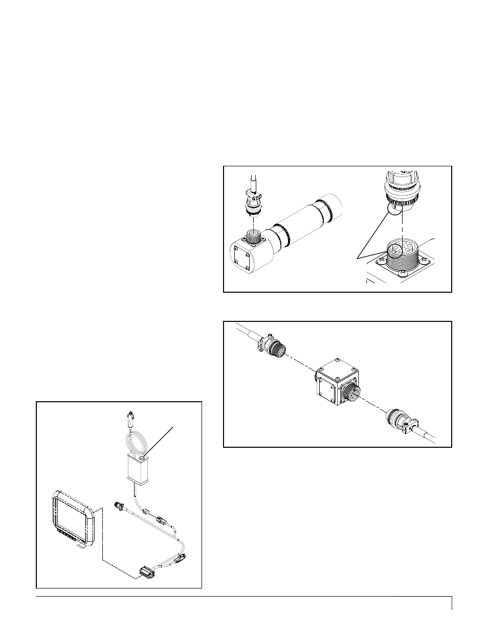
Attach the selected cable to the TruLink
Pin. Be sure to align the pins inside the
cable connector with the holes on the
TruLink connecting base. The tab and slot must
align with each other in order to ensure a positive
connection. See fi gure 1C.
1
Run all Cables next to the hydraulic hoses
running along prime movers arms and
or boom. It is recommended to zip tie
the Cables to the hydraulic hoses. The Cables
should be run in a manner that does not expose
the Cables to excessive heat or pinching.
2
TRULINK PIN / CABLE CONNECTION
Figure 1C
On class 3 & 4 TruLink systems it is
recommended to use the provided
Junction Box and Jib Cable. Installing
a Junction Box and Jib Cable close to the Anchor
Drive will allow for easy disconnect. Using a Jib
Cable near the Anchor Drive will prevent damage
to the Main Cable and is easier to replace in the
event the cable is damaged. See fi gure 2C.
1a
Ensure Cable connections are solid and not binding or pinched.
Depending on the distance from the Anchor Drive to the Display select the appropriate Cable(s). All TruLink systems have
a Main Cable and an Extension Cable.
Main Cable will connect to the display harness and the TruLink Pin if the length is suffi cient.
Extension Cable (if necessary) connects the Main Cable to the TruLink Pin.
Note: Ensure that the cable(s) have enough “slack” to allow for full range or movement . Most cables can be run next to
the hydraulic hoses.
Figure 2C
Align Slot with Tab
(All Connections)
The Battery Back-Up Cable plugs into the Display Power Harness as
shown in fi gure 3D.
Use the ON / OFF switch located on top of the Battery Box to power on
and power off the Display.
BATTERY BACK-UP CABLE CONNECTION
On / Off
Switch