ONICON F-4000 Series User Manual
Page 13
11451 Belcher Road South, Largo, FL 33773 • USA • Tel +1 (727) 447-6140 • Fax +1 (727) 442-5699 • [email protected]
F-4000 Series Ultrasonic Flow Meter Manual 05/15 - 0707-13 / 18838
Page 13
3.3.3 Reflect Mode Mounting Using Frames and Spacer Bar
1. Prepare the pipe surface as described in section 3.3.2.
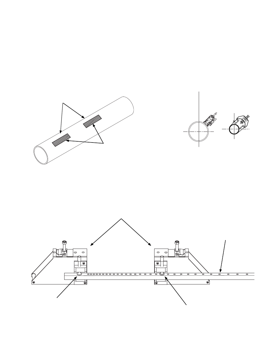
2. On a flat surface, assemble the hardware as shown in the drawing below.
3.3.2 Preparing the Pipe
Once a suitable section of straight pipe has been located, the pipe surface must be
prepared. Refer to the Site Installation Details document provided with the installation
hardware to determine the transducer spacing dimensions. Prepare the pipe surface as
shown below. Clean and de-grease two rectangles where the transducers will be located.
Use the small sanding block provided with the installation hardware as necessary to
remove any grit, corrosion, rust, loose paint or other contaminants. The cleaned surface
should extend at least ½” beyond the length and width of the transducers.
Always install hardware at the 10:00 or 2:00 position on horizontal pipes. This prevents
the flow meter from being affect by air trapped at the top of the pipe.
Refer to site installation details
document for transducer spacing.
Prepare mounting
locations for transducers.
For horizontal pipes, locate transducers at
the 10:00 or 2:00 position.
Orient mounting brackets as shown.
Reference hole
Refer to the Site Installation Details document
provided with the installation hardware to
determine the correct hole location.
Numbered index holes