ONICON F-4000 Series User Manual
Page 24
11451 Belcher Road South, Largo, FL 33773 • USA • Tel +1 (727) 447-6140 • Fax +1 (727) 442-5699 • [email protected]
F-4000 Series Ultrasonic Flow Meter Manual 05/15 - 0707-13 / 18838
Page 24
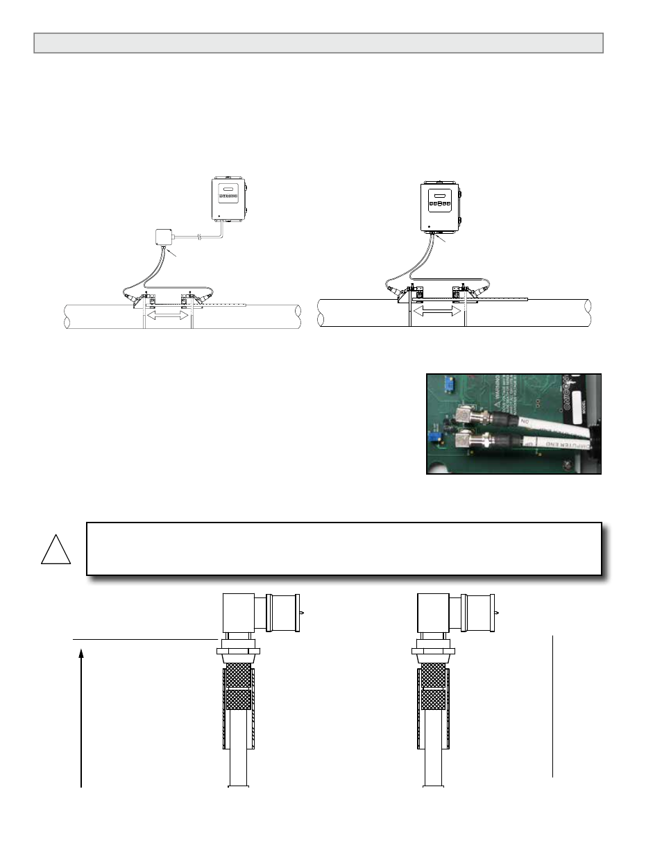
3.4 CONNECTING THE TRANSDUCER SIGNAL CABLES
ONICON F-4000 transducer cables are special purpose coaxial cables. Care must be taken when
installing the cables to ensure that electrical noise will not affect the performance of the meter.
The cables must NOT be bundled or run in conduit with any other signal or power cables. The
maximum allowable cable length is 300 ft.
To install the cables, first locate and install the wall-mount electronics enclosure and the
transducers.
The transducer cables are provided with connectors already
installed at one end of the cable. Install this end of each
cable at the electronics enclosure as shown below using the
right angle adapters provided. When installing the cable,
avoid routing it close to strong sources of electrical noise,
and do not install cables in raceways with power or other
signal cables.
Once the correct cable length has been determined, install
the F-connectors provided to terminate the end of each cable.
Strain relief provided
FLOW
TYPICAL INSTALLATION WITHOUT CONDUIT
WARNING
For proper operation, cables must not be bundled or run in conduit with any other signal or power
cables.
!
UP
DN
ASSEMBLED IN FIELD BY
CUST
OMER
ENCLOSURE END (REF
.)
ENCLOSURE END
ENCLOSURE END
UP
DN
NOTE: "L" MAXIMUM CABLE LENGTH IS 300 FT
. CONT
ACT ONICON IF LONGER CABLE RUNS
ARE REQUIRED.
"L"
6" (TYP
.)
CABLE
NPT
ADAPTERS
CABLE MARKERS
STRAIN RELIEF FITTINGS
F-CONNECT
ORS
HEA
T
SHRINK
Strain relief provided
FLOW
TYPICAL INSTALLATION WITH CONDUIT