ONICON F-4000 Series User Manual
Page 28
11451 Belcher Road South, Largo, FL 33773 • USA • Tel +1 (727) 447-6140 • Fax +1 (727) 442-5699 • [email protected]
F-4000 Series Ultrasonic Flow Meter Manual 05/15 - 0707-13 / 18838
Page 28
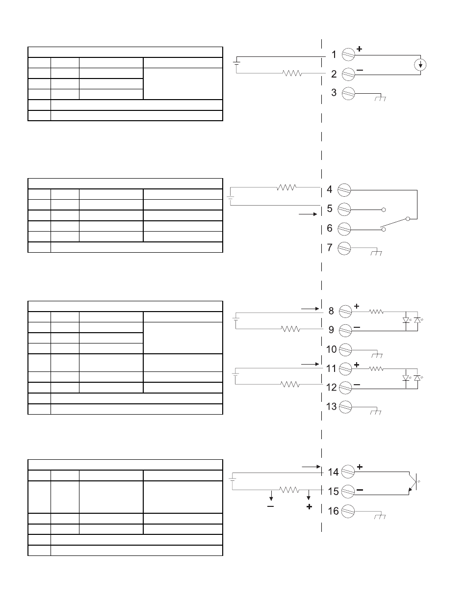
Analog Output (IO1)
Term #
Function
Description
1
(+) 4 - 20 loop supply
Loop (externally) powered
4 - 20 mA output
2
(-) 4 - 20 loop return
3
Shield
RL=250 W typical, 750 W maximum
Vc=24 VDC typical / 30 VDC maximum
= 0 to 750
Vc
30Vdc
max
R
L
Vc
R
L
C
NO
NC
I
ON
= 100
(max)
mA
30Vdc
max
Vc
R
L
R
L
I
ON
= 4
(min)
- 20
(max)
mA
I
ON
= 4
(min)
- 20
(max)
mA
500Ω
500Ω
30Vdc
max
30Vdc
max
Vc
Vc
R
L
I
ON
= 10
(max)
mA
Vo
30Vdc
max
Relay Output (RELAY OUTPUT)
Term #
Function
Description
4
Common
Relay Common
5
Normally Open
Relay Output
6
Normally Closed
Relay Output
7
Shield
RL=300 W minimum
Digital Inputs (NO TOT, CLR TOT)
Term #
Function
Description
8
(+) No Totalizer
Digital input used to inhibit
totalizer
9
(-) No Totalizer
10
Shield
11
(+) Reset Totalizer
Digital input used to reset
totalizer to zero
12
(-) Reset Totalizer
13
Shield
Vc=2-10VDC; Then R
L
=OW
Vc=>10≤30VDC; Then R
L
=(Vc-10)/.02
Pulse Output (PULSE OUTPUT)
Term#
Function
Description
14
(+) Pulse Output
Programmable pulse
output. Optically isolated
(externally powered) open
collector.
15
(-) Pulse Output
16
Shield
Vc= +30 VDC maximum
RL = 3K W minimum
USER CONNECTIONS F-4000 INPUTS AND OUTPUTS