ONICON F-4000 Series User Manual
Page 21
11451 Belcher Road South, Largo, FL 33773 • USA • Tel +1 (727) 447-6140 • Fax +1 (727) 442-5699 • [email protected]
F-4000 Series Ultrasonic Flow Meter Manual 05/15 - 0707-13 / 18838
Page 21
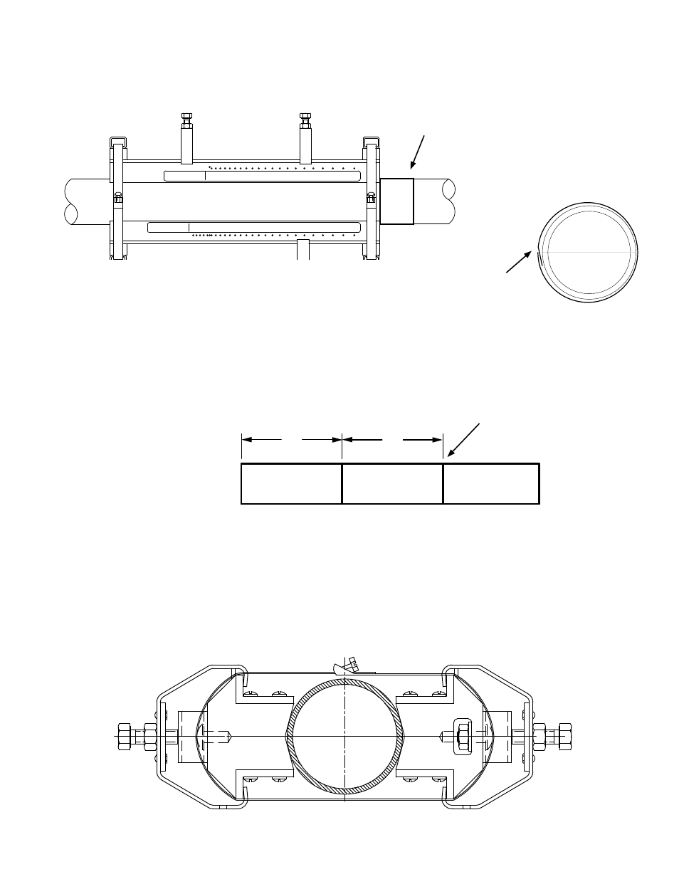
4. Wrap the Mylar spacing guide around the pipe placing it against the end of the track
mount assemblies. Ensure that it is snug around the pipe and mark along the
overlapping edge.
5. Remove Mylar spacing guide and lay it out on a flat surface. Either measure the exact
distance half-way between the overlap edge and the mark at the overlap, or fold the
guide from the overlap edge to overlap mark and draw a line at the fold or halfway
point.
DIRECT MODE SPACING
9
2
0 1
4 5
3
8
6 7
14
11
10
13
12
16
15
18
17
20
19
21
23
22
24
25
REFLECT MODE SPACING
9
REF5
8
6 7
14
12
11
10
13
16
15
18
17
20
19
21
23
22
24
25
O.D. RANGE 1/4"-5"
TRACK 400
TRACK 400
O.D. RANGE 1/4"-5"
6. Reinstall the spacing guide and tape it in place. Use the edge of the guide to align each
assembly bracket as shown.
7. Rotate the track assemblies until the center of one track aligns with the center line
on the spacer guide, and the center of the other track aligns at the point where the
spacer guide ends meet. The tracks should now be 180° apart. Tighten both mounting
straps to secure the assembly to the pipe. Do not over tighten.
Draw the guide tightly
around the pipe and mark
at the overlapping edge.
50%
50%
1.5869
Overlap edge mark
Wrap Mylar spacing guide
around pipe and mark
along overlapping edge.