ONICON F-4000 Series User Manual
Page 16
11451 Belcher Road South, Largo, FL 33773 • USA • Tel +1 (727) 447-6140 • Fax +1 (727) 442-5699 • [email protected]
F-4000 Series Ultrasonic Flow Meter Manual 05/15 - 0707-13 / 18838
Page 16
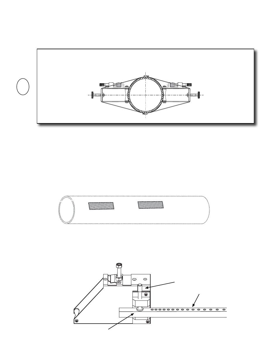
2. To prepare the pipe, temporarily position a mounting bracket on the pipe where you
will be mounting it. Ensure that the pipe surface is smooth without any raised areas
(seams, etc.) With a pencil, marker or chalk, draw a generous rectangle around the
bracket. Clean and de-grease the area within the rectangle. Use the small sanding block
provided with the installation hardware as necessary to remove any grit, corrosion,
rust, loose paint or other contaminants. Be sure to wipe the surface clean after sanding.
The cleaned surface should extend at least ½” beyond the length and width of the
mounting bracket.
3. Attach the spacer bar to one of the mounting brackets at the reference hole.
3.3.5 Direct Mode Mounting Using Brackets and Spacer Bar
1. Once the installation site selection process described in section 3.2 is complete,
prepare the pipe where the first sensor will be mounted.
IMPORTANT NOTE
Direct mode mounting requires that transducers be installed on opposite sides of the pipe. For
horizontal pipes, the transducers should be located at the 3 o’clock and 9 o’clock positions.
i
Clamping Screw
Spacer Bar
Reference Hole