ONICON F-4000 Series User Manual
Page 45
11451 Belcher Road South, Largo, FL 33773 • USA • Tel +1 (727) 447-6140 • Fax +1 (727) 442-5699 • [email protected]
F-4000 Series Ultrasonic Flow Meter Manual 05/15 - 0707-13 / 18838
Page 45
SECTION 6.0: COMMISSIONING FOR ONICON
CLAMP-ON ULTRASONIC FLOW METERS
Please read all installation instructions carefully before proceeding. Wiring diagrams are located in an earlier
section of this manual. Use the meter certificate of calibration to verify that the specified installation &
operating parameters match the actual conditions at the location where the meter is installed. A worksheet
for checking off these steps and recording measured values is located in section 5.3.
6.1 HELPFUL HINTS FOR START-UP AND COMMISSIONING
Please read these helpful hints before proceeding with the commissioning procedure on the next page.
1. ONICON flow meters are individually calibrated for a particular application. Be sure to verify
the pipe size and location.
2. The ultrasonic flow sensing systems will not work with an empty pipe.
3. When measuring analog output signals, remember that current (mA) must be measured in
series, while voltage is measured in parallel. If the 4-20 mA signal is already connected to a
control system, you must break the connection and measure the signal in series.
4. When measuring frequency outputs in Hz, take your multimeter out of “auto range mode” and
manually set the range for a voltage level above 15 VDC. This will prevent false readings
when signal is not present.
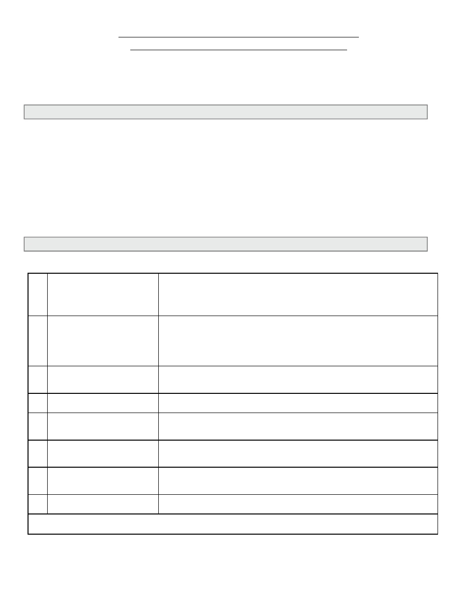
6.2 COMMISSIONING PROCEDURE
Please read the entire procedure before proceeding. A worksheet for checking off the following steps
and recording measured values provided in Section 5.3.
1.
Confirm that the flow meter is
being installed in accordance
with Sections 1.8 and 3.2 of
this manual.
Confirm that the installation location is removed from any sources of strong
electrical interference and that the enclosure is mounted on a vibration-free
surface.
Confirm that the transducer signal cables are run in dedicated conduit
without other signal or power cables.
2.
Confirm flow meter location. Confirm adequate straight pipe run to achieve desired results. Is the
meter located in the correct location as required by the plans? Compare
actual straight pipe upstream and downstream of the meter location to
recommended distances identified in this manual. Contact ONICON to
discuss specifics of your application. If straight pipe run is very short,
consult ONICON PRIOR to commissioning the meter.
3.
Confirm pipe size.
Confirm that the meter is tagged for the pipe size in which it is installed.
When in doubt, measure the circumference of the pipe. Pipe O.D. =
(circumference / 3.14) – (insulation thickness x 2).
4.
Verify the type of fluid used
in the piping system.
Confirm that the fluid specified on the flow meter certificate of calibration
matches the fluid flowing in the piping system.
5.
Confirm control system
programming.
Confirm that the control system input points are properly configured for
the analog output range, pulse scale factor and/or relay output function
identified on the calibration certificate & meter tag.
6.
Confirm connection to the
correct ONICON display or
Btu meter (if ordered).
Confirm that the flow meter serial number matches the ONICON display or
Btu meter serial number (when ordered together).
7.
Verify output signal wiring.
Verify that the wiring is correct as shown in this manual and/or the
additional wiring diagram provided with the ONICON display or Btu meter.
If in doubt, contact ONICON for assistance before proceeding further.
8.
Confirm correct supply
voltage.
Verify that the supply voltage is within specified limits.
11.5 – 28.5 VDC or 90 – 240 VAC 50/60Hz
The following steps require flow in the pipe. Flow signal readings should be taken while holding the flow rate
constant, if possible. Otherwise, take the various output readings as quickly as possible.