ONICON F-4000 Series User Manual
Page 22
11451 Belcher Road South, Largo, FL 33773 • USA • Tel +1 (727) 447-6140 • Fax +1 (727) 442-5699 • [email protected]
F-4000 Series Ultrasonic Flow Meter Manual 05/15 - 0707-13 / 18838
Page 22
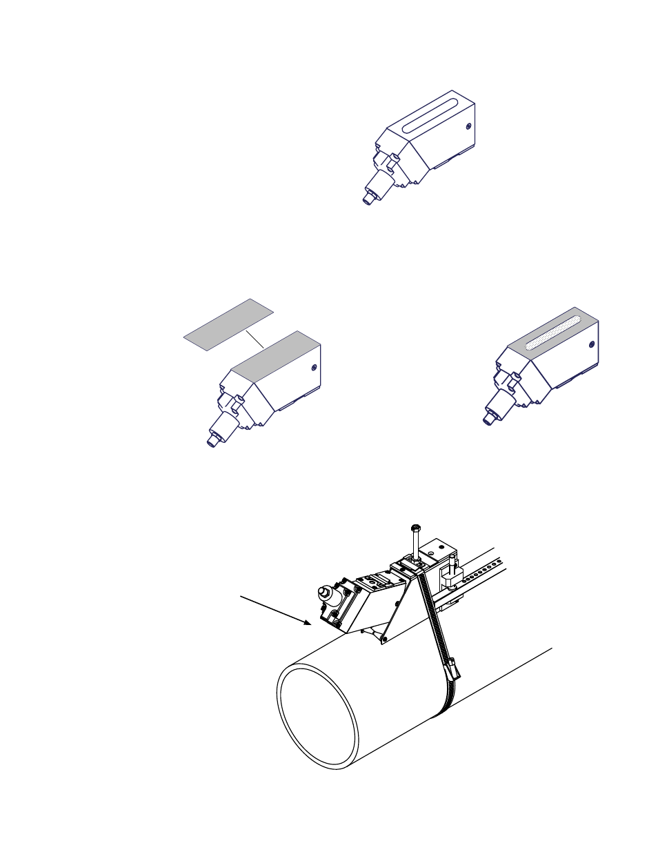
3.3.7 Installing Transducers In Bracket and Spacer Bar Hardware
1. Apply the dry coupling pad to the transducer as show below.
Apply a continuous
lengthwise 1/2” wide bead
of coupling compound
down the center of the
transducer.
2. This step only applies to reflect mount transducers installed on copper and steel pipes.
For all other applications, skip to step 3.
Apply the dry coupling pad to the transducer as show below.
Place the dry coupling
pad on the transducer.
Gently press down just
enough to seat and center
the pad.
Apply a second bead
of coupling compound
down the center of the dry
coupling pad.
3. Slide the transducer into the mounting bracket back end first, aligning the angled edge
of the transducer with the angled edge of the bracket. Do not allow the bottom of the
transducer to make contact with the pipe until it butts against the mounting bracket
stop. Push down firmly on the transducer to mate with pipe.
When installing the transducer,
do not allow the bottom face to
touch the pipe surface until it is
fully inserted to the stop.