ONICON F-4000 Series User Manual
Page 18
11451 Belcher Road South, Largo, FL 33773 • USA • Tel +1 (727) 447-6140 • Fax +1 (727) 442-5699 • [email protected]
F-4000 Series Ultrasonic Flow Meter Manual 05/15 - 0707-13 / 18838
Page 18
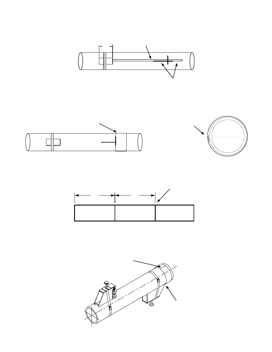
7. Remove the bracket from the spacer bar and then remove the spacer bar from the
bracket that is strapped to the pipe. Using the spacer bar as a straight edge, draw a line
down the center of the pipe intersecting the mark made at the center of the tapered
roller and the line drawn against the edge of the bracket as shown below.
8. Wrap the Mylar spacing guide around the pipe so that the left edge is against the
transducer edge mark. Arrange so that one end overlaps the other. Ensure that it is
snug around the pipe and mark along the overlapping edge.
9. Remove Mylar spacing guide and lay it out on a flat surface. Either measure the exact
distance half-way between the overlap edge and the mark at the overlap, or fold the
guide from the overlap edge to overlap mark and draw a line at the fold or halfway
point.
50%
50%
1.5869
50%
50%
1.5869
50%
50%
1.5869
10. Reinstall the spacing guide; its edge abutting the bracket edge mark on the pipe and the
overlapping edge in line with the line drawn down the center of the pipe. Tape it in
this position on the pipe. Take the second bracket and place it against the edge of the
guide with its tapered roller centered on the half way mark drawn on the guide.
Draw line using spacer
bar as edge.
Spacer bar
Mylar spacing guide
Overlap edge mark
Draw the guide tightly
around the pipe and mark
at the overlapping edge.
Mylar spacing guide aligned
with marks on pipe.
Bracket aligned with edge of
guide and centered on marks
on the guide.