F-connector installation instructions – ONICON F-4000 Series User Manual
Page 25
11451 Belcher Road South, Largo, FL 33773 • USA • Tel +1 (727) 447-6140 • Fax +1 (727) 442-5699 • [email protected]
F-4000 Series Ultrasonic Flow Meter Manual 05/15 - 0707-13 / 18838
Page 25
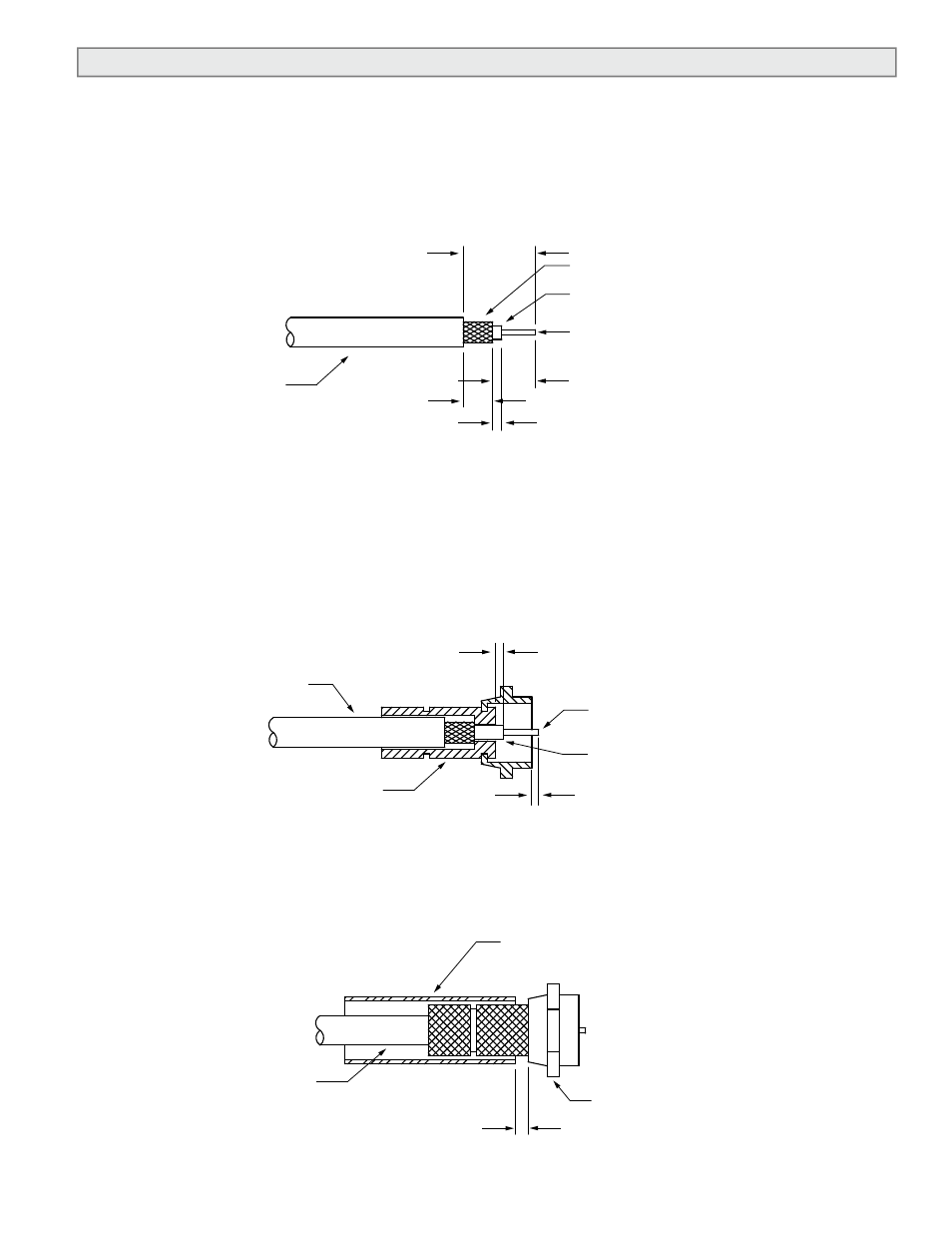
3.5 INSTALLING THE F-CONNECTORS
Prior to installing the F-connectors, slide the upstream and downstream cable markers over the
ends of the cables followed by the strain relief and NPT adapters.
3.5.1 Cable Preparation
Strip and trim to length as shown. Do not push copper braid back over jacket.
3.5.2 Cable & Connector Assembly
Thread cable into connector until the dielectric slightly protrudes from the end of the
barrel. The center conductor should protrude approximately 1/16” beyond the connector
body as shown.
3.5.3 Final Assembly
Place shrink tubing over the connector and shrink in place with hot air gun.
CABLE
"F" CONNECTOR
CABLE
DIELECTRIC
CENTER
CONDUCTOR
1/16"
F-CONNECTOR INSTALLATION
INSTRUCTIONS
Prior to installing the F-Connectors, slide upstream and downstream cable markers
over the ends of the cables.
Cable Preparation
Strip and trim to length as shown.
(Do not punch braid back over jacket.)
9/16”
DIELECTRIC
CENTER
CONDUCTOR
5/16”
1/4”
CABLE
1/16” - 3/32” DIELECTRIC
EXTENDS BEYOND BRAID
Cable & Connector Assembly
Thread cable into connector until the
dielectric slightly protrudes from the
end of the barrel. The center
conductor should protrude
approximately 1/16” beyond the
connector body as shown.
1/32” MAX. PROJECTION
OF DIELECTRIC
Final Assembly
Place shrink tubing over connector
and shrink in place with hot air gun.
SHRINK SLEEVE
(DWP125 - 1/2 X 3/4”)
F-CONNECTOR
P/N SPCF 59 I
1/8” (MIN)
COPPER BRAID
CABLE
"F" CONNECTOR
CABLE
DIELECTRIC
CENTER
CONDUCTOR
1/16"
F-CONNECTOR INSTALLATION
INSTRUCTIONS
Prior to installing the F-Connectors, slide upstream and downstream cable markers
over the ends of the cables.
Cable Preparation
Strip and trim to length as shown.
(Do not punch braid back over jacket.)
9/16”
DIELECTRIC
CENTER
CONDUCTOR
5/16”
1/4”
CABLE
1/16” - 3/32” DIELECTRIC
EXTENDS BEYOND BRAID
Cable & Connector Assembly
Thread cable into connector until the
dielectric slightly protrudes from the
end of the barrel. The center
conductor should protrude
approximately 1/16” beyond the
connector body as shown.
1/32” MAX. PROJECTION
OF DIELECTRIC
Final Assembly
Place shrink tubing over connector
and shrink in place with hot air gun.
SHRINK SLEEVE
(DWP125 - 1/2 X 3/4”)
F-CONNECTOR
P/N SPCF 59 I
1/8” (MIN)
COPPER BRAID