Repeat procedure for the second transducer, Transducer clamping screw, Reference hole – ONICON F-4000 Series User Manual
Page 23: Clamping screw, Reflect mode, O.d. range 1/4"-5, Track 400
11451 Belcher Road South, Largo, FL 33773 • USA • Tel +1 (727) 447-6140 • Fax +1 (727) 442-5699 • [email protected]
F-4000 Series Ultrasonic Flow Meter Manual 05/15 - 0707-13 / 18838
Page 23
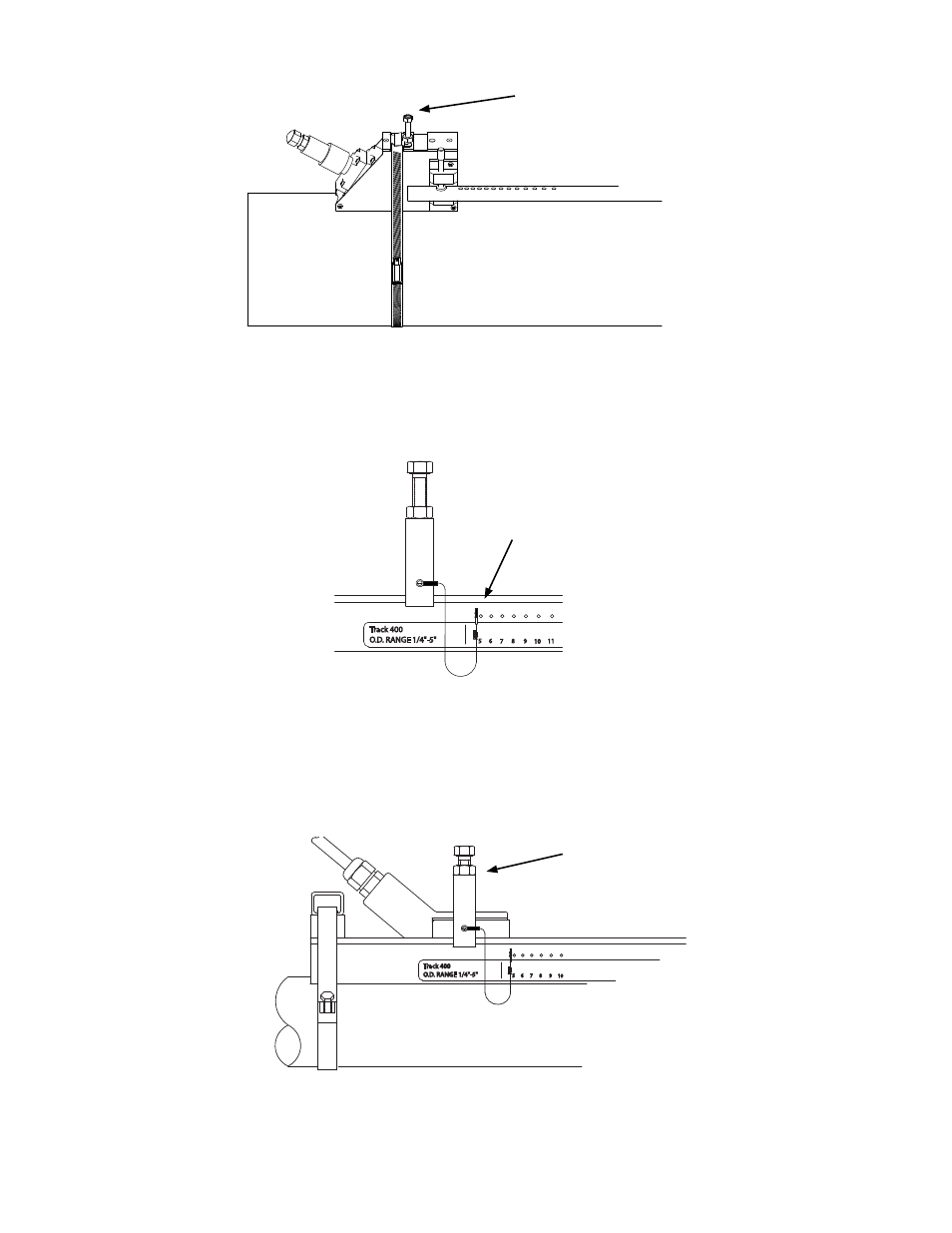
Transducer Clamping Screw
4. Tighten the transducer clamping screw to hold the transducer firmly in place.
Do not over tighten the screw.
5. Repeat procedure for the second transducer.
3.3.8 Installing Transducers In Track Mount Hardware
1. Insert the index pin into the reference hole.
REFLECT MODE
(71.1)
3.0
(76.2)
2.8
REF
O.D. RANGE 1/4"-5"
6 7
5
Track 400
17
REFLECT MODE SPACING
13
9 10
8
12
11
15
14
16
19
18
20
22
21
23
CUSTOMER'S PIPE
25
24
REF
O.D. RANGE 1/4"-5"
6 7
5
Track 400
9 10
8
11
REF
O.D. RANGE 1/4"-5"
6 7
5
Track 400
9 10
8
15.94
(405)
Reference hole
2. Repeat step 1 and 2 in Section 3.3.7 as necessary to apply couplant and pad to
tranducer.
3. Place the transducer between the track rails, slightly behind the pin and under the
clamping screw assembly. Slide it forward until it butts firmly against the reference
pin. Once the transducer is in place, secure it with the sensor clamping screw. Do not
over tighten.
REFLECT MODE
(71.1)
3.0
(76.2)
2.8
REF
O.D. RANGE 1/4"-5"
6 7
5
Track 400
17
REFLECT MODE SPACING
13
9 10
8
12
11
15
14
16
19
18
20
22
21
23
CUSTOMER'S PIPE
25
24
REF
O.D. RANGE 1/4"-5"
6 7
5
Track 400
9 10
8
11
REF
O.D. RANGE 1/4"-5"
6 7
5
Track 400
9 10
8
15.94
(405)
4. Repeat procedure for the second transducer.
Clamping screw