ONICON F-4000 Series User Manual
Page 14
11451 Belcher Road South, Largo, FL 33773 • USA • Tel +1 (727) 447-6140 • Fax +1 (727) 442-5699 • [email protected]
F-4000 Series Ultrasonic Flow Meter Manual 05/15 - 0707-13 / 18838
Page 14
3. Install the mounting straps as shown below. For larger pipes, use multiple straps
connected end-to-end to increase the length of each strap. Leave enough slack in the
straps to allow the assembly to be correctly positioned on the pipe.
4. Move the hardware assembly to its final position on the pipe. Align the brackets
with the prepared surface for each transducer as shown below, ensuring that the
entire assembly is properly oriented along the axis of the pipe. Tighten the assembly
firmly on the pipe. Do not over tighten the straps.
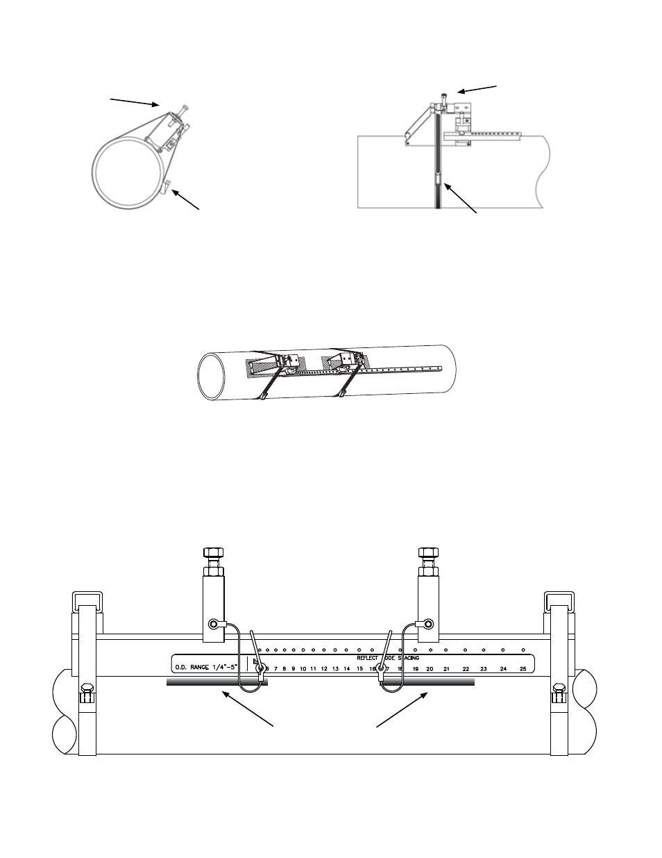
3.3.4 Reflect Mode Mounting Using Track Mount Hardware
1. Prepare the pipe surface as described in section 3.3.2.
2. Place the track mount hardware assembly at the 10:00 or 2:00 position on the pipe at
the desired mounting location. Ensure that it is a clean, smooth area without any raised
spots or seams.
TRACK 400
Prepared Surfaces
Wrap the first mounting strap
around the pipe and under the
spring clip on top of the mounting
bracket. Make sure to position
it so there is easy access to the
adjustment screw. Repeat this
procedure for the second mounting
bracket.
Spring clip
Adjustment screw
Adjustment screw
Spring clip