ONICON F-4000 Series User Manual
Page 17
11451 Belcher Road South, Largo, FL 33773 • USA • Tel +1 (727) 447-6140 • Fax +1 (727) 442-5699 • [email protected]
F-4000 Series Ultrasonic Flow Meter Manual 05/15 - 0707-13 / 18838
Page 17
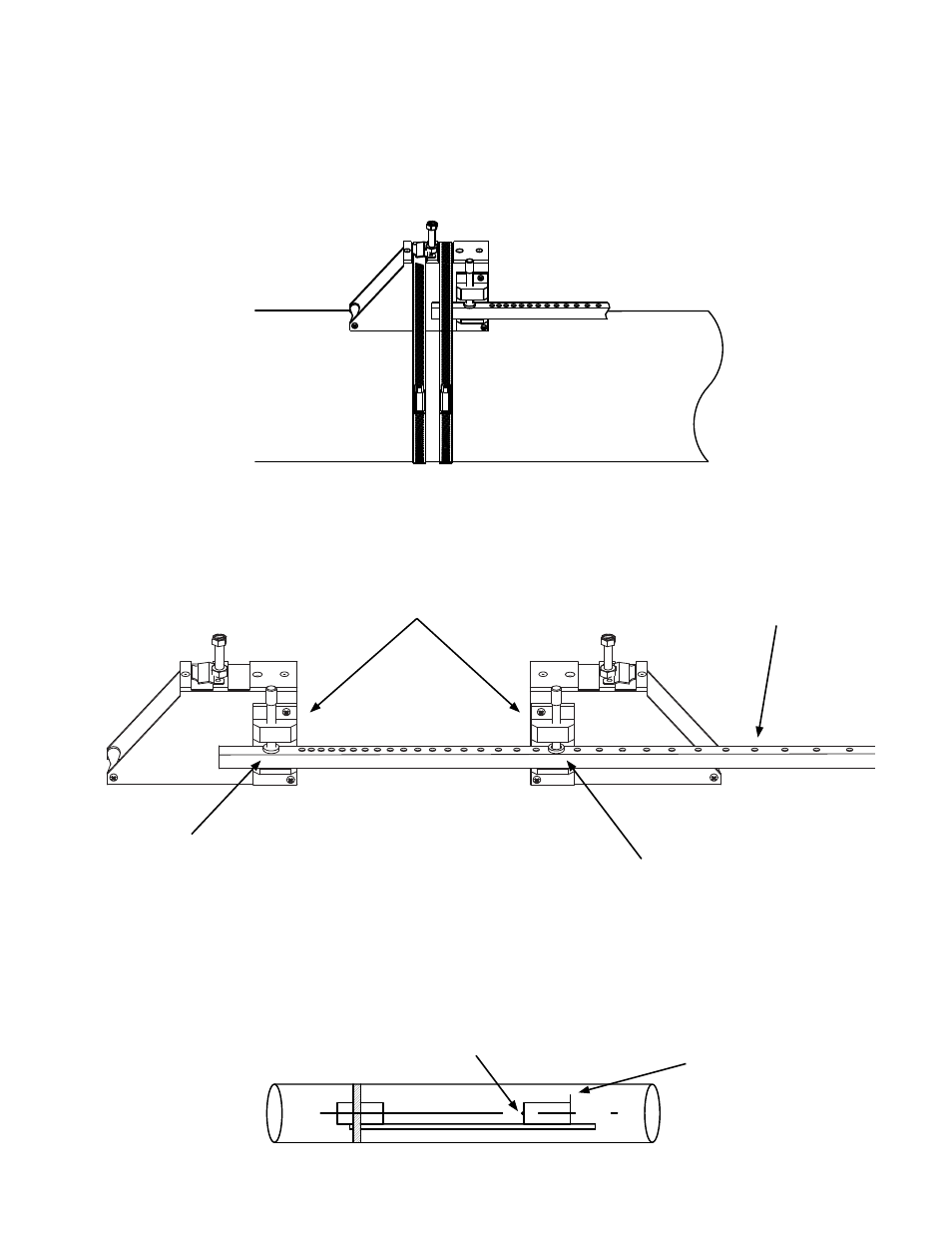
5. Attach the second bracket to the spacer bar at the numbered index hole specified on
the site installation details document provided with the installation hardware. Note
that the angled end of the bracket must be facing away from the other mounting
bracket.
6. Check to ensure that this bracket is lined up on the center of the pipe. While holding
the bracket centered on the pipe, place a mark (with pencil or chalk) at the center of
the tapered roller at the bottom of the bracket as shown below. Next, mark along the
edge of the bracket as indicated in the drawing below.
4. Position the mounting bracket and spacer bar in the center of the cleaned area and
secure it in place with a mounting strap as shown below. Make sure the mounting
strap tightening screw is facing up. Note that the angled end of the bracket must be
facing away from where the other bracket will be mounted. While tightening the strap,
check to ensure that the bracket remains centered on the pipe. (The bracket is centered
on the pipe when the bottom edges of both aluminum side plates on the bracket are in
full contact with the pipe surface.)
50%
50%
1.5869
Orient mounting brackets as shown.
Reference hole
Refer to the Site Installation Details document
provided with the installation hardware to
determine the correct hole location.
Numbered index holes
Place mark at center
of tapered roller.
Draw line along edge
of bracket.