2 analogue – Watson-Marlow 620U User Manual
Page 35
Watson-Marlow 620UN, 620U, 620SN, 620S User Manual
35
UN, U
Select Trim from the Setup menu or the Analogue setup menu using the UP or
DOWN keys and press ENTER to confirm your choice.
Apply the low process analogue signal to (620UN) the i/p terminal of the
Analogue 1 connector or (620U) pin 4 of the lower D-connector as instructed
in the display. See 16.2 Analogue. While the signal is being applied, press
ENTER to record the signal as a calibration point.
Apply the maximum process control signal. While the signal is being applied,
press ENTER to record the signal as a calibration point.
Apply 50% of the maximum process control signal. While the signal is being
applied, press ENTER to record the signal as a calibration point.
If a mistake is made, press STOP at any point in the sequence, and the pump
displays the previous screen.
The final press on ENTER causes the pump to display a confirmation screen
and then redisplay the screen from which it entered the trim sequence: the
Setup menu or the Analogue setup menu.
The pump calculates a linear response from low to mid and from mid to high, and
records the results as a new analogue input calibration graph.
If any of the three signals match, a warning screen is displayed before the confir-
mation screen appears, and the trim is ignored.
Note: By applying the maximum process control signal when the minimum is
requested and vice versa, inverted responses can be set up.
Note: Resetting factory defaults clears the trim calibration values.
16.2 Analogue
When the pump is under remote control, it tracks an analogue signal from the user’s
remote control system to the i/p terminal of the Analogue 1 connector at the rear
of the pump within the ranges 4-20mA, 0-10V or 1-5V. The Analogue option in the
Setup menu allows the user to configure the pump to operate with his remote con-
trol system.
When the pump is under remote control, it tracks an analogue signal from the user’s
remote control system to pin 4 of the lower D-connector at the rear of the pump
within the ranges 4-20mA, 0-10V or 1-5V. The Analogue option in the Setup menu
allows the user to configure the pump to operate with his remote control system.
UN, U
U
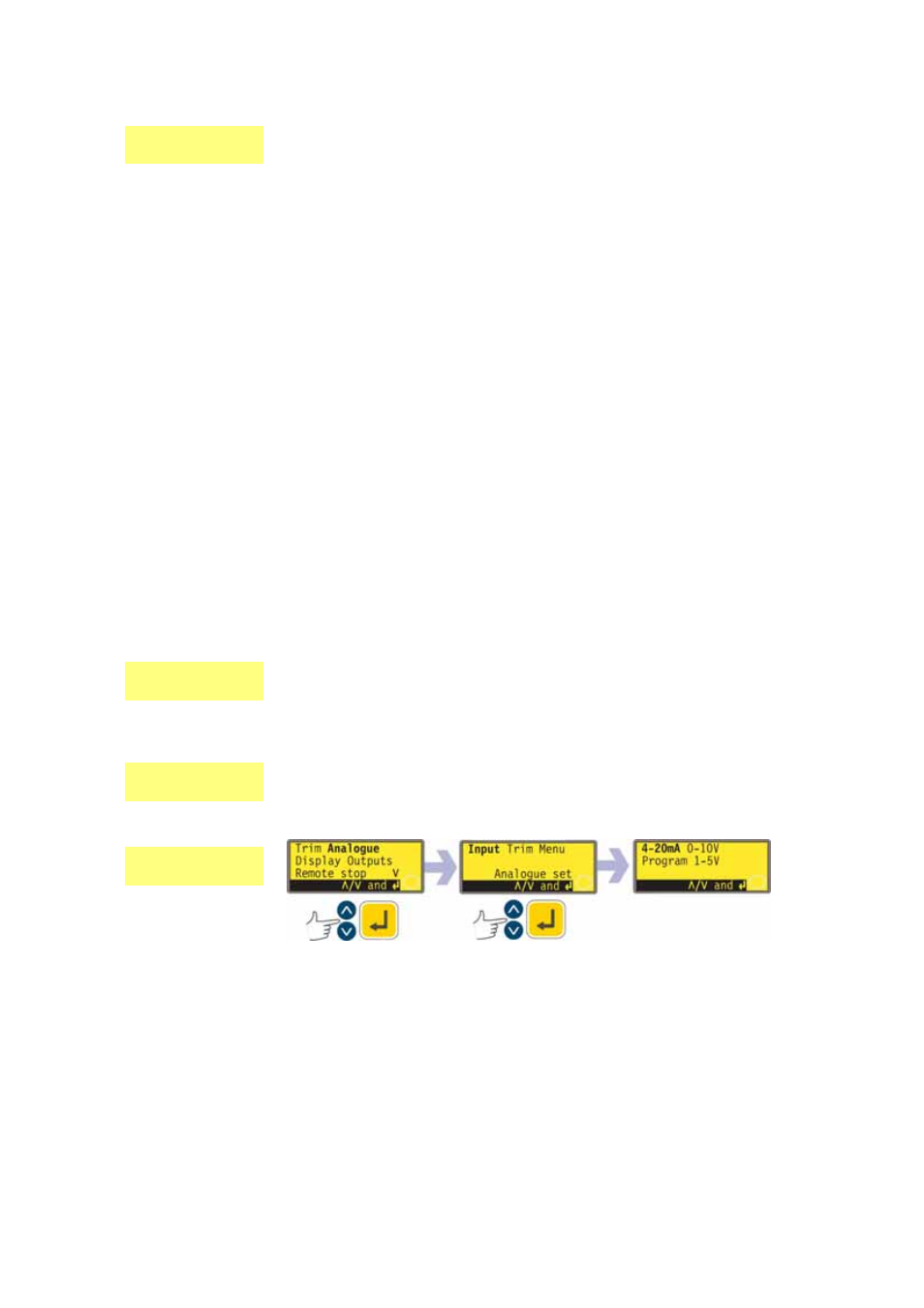
Select Analogue from the Setup menu using the UP or DOWN keys and press
ENTER to confirm your choice.
Three options are displayed: Input, Trim and Menu.
UN, U