6 run/stop input, 7 direction input, 8 auto / manual toggle input – Watson-Marlow 620U User Manual
Page 62
Watson-Marlow 620UN, 620U, 620SN, 620S User Manual
62
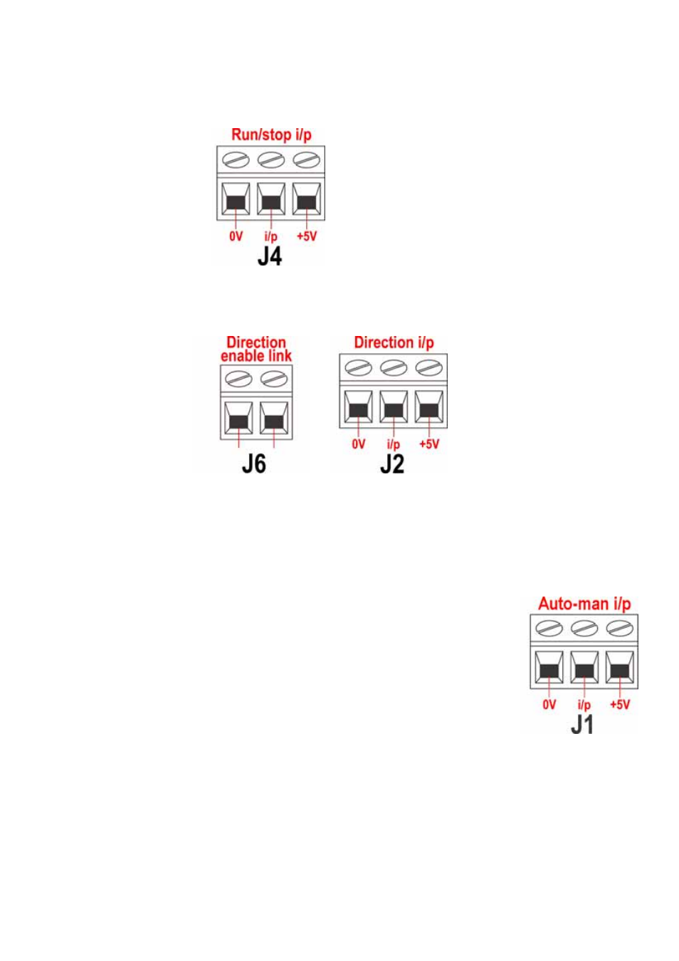
20.6 Run/stop input
Remote run/stop: connect a remote switch between the
i/p terminal and the +5V terminal of the Run/stop i/p
connector (J4). Alternatively a logic input may be applied
to the i/p terminal, ground to the 0V terminal. High input
stops the pump, low input runs the pump. With no connec-
tion or with the switch open, the pump will default to run-
ning. To change or set the sense of the run/stop input, see
16.5 Remote stop in the Setup menu.
20.7 Direction input
To enable remote direction control
and disable the DIRECTION
(SHIFT, 1) key on the keypad,
link the terminals of the Direction
enable link connector (J6).
Important: Apply no voltage
whatever to the Direction
enable link. Connect a remote
switch between the +5V terminal
and the i/p
terminal of the
Direction i/p connector (J2). Open
switch for clockwise rotation,
closed switch for counter-clockwise rotation. Alternatively a logic signal may be
applied to the i/p terminal and the 0V terminal of the Direction i/p connector (J2).
Low input for clockwise rotation, high input for counter-clockwise rotation. With no
connection the pump defaults to clockwise rotation.
20.8 Auto / manual toggle input
Connect a remote switch between the +5V terminal and the
i/p terminal of the Auto-man i/p connector (J1). Closed
switch for automatic control; open switch for manual control.
Alternatively a logic input may be applied to the i/p
terminal of the Auto-man i/p connector, ground to the 0V
terminal. High input for automatic control; low input for man-
ual control.