Watson-Marlow 620U User Manual
Page 83
Watson-Marlow 620UN, 620U, 620SN, 620S User Manual
83
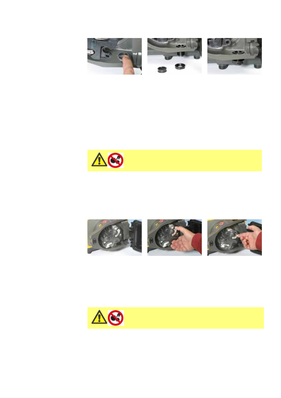
Connect waste pipe work to the waste port using the coupling adaptor supplied.
Push out the blanking plug. Drop the threaded waste fitting into place. Secure
it with the supplied locking nut. Fully tighten by hand. Ensure that there is ade-
quate clearance underneath the pumphead. Waste pipe work should run to a
suitable container or drain.
The leak detector installation procedure is included in the leak detector kit.
If unsure of an installation please contact your local Technical Support Office.
26.5 620RE, 620RE4 and 620R
general operation
Always isolate the pump from the mains power
supply before opening the guard or performing
any positioning, removal or maintenance.
Opening the pumphead guard
Unlock the guard with the 5mm Allen key provided (or a screwdriver).
Open the guard to its full extent. This creates the maximum clearance between
the tube ports and guard to remove the tubing.
Engaging/disengaging the rollers
The extent of travel of the roller release levers is clear from pictures 2 and 3
above. Do not try and force the levers beyond their normal extent of travel as
this will damage the rotor.
To engage the rollers snap the roller release levers counter-clockwise making
sure that the rollers lock out against the tubing. To disengage the rollers, snap
the release levers clockwise to their disengaged position. For high pressure tub-
ing elements or four roller pumpheads, a 5mm Allen key can be used to aid
leverage when engaging/disengaging the rollers with the release levers.
Make sure that fingers are clear of the rollers
and the front face of the rotor hub when using
the roller release levers.