Watson-Marlow 620U User Manual
Page 66
Watson-Marlow 620UN, 620U, 620SN, 620S User Manual
66
U
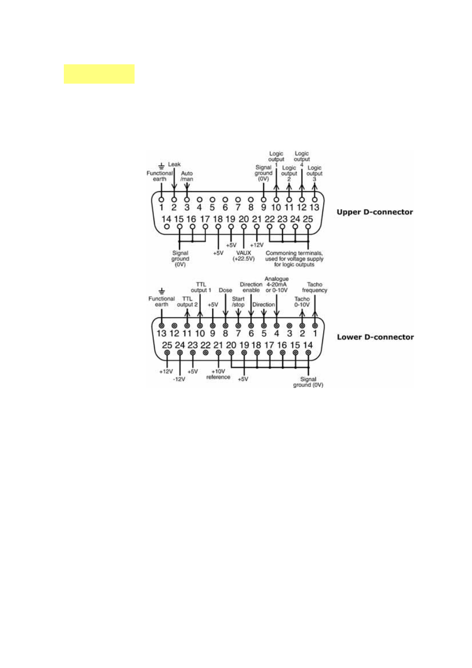
21 Automatic control wiring
without the 620N module
Interfacing the pump with other devices is by means of three D-connectors at the
rear of the pump. There are two 25-way D-connectors. The top one is male, the
bottom one is female. Mating female and male connectors, screened for EMC com-
patibility, must be conventionally soldered to screened control cables.
Recommended control cable: 7 strands 0.2mm, 24AWG, screened, circular, up to 25-
core. The cable screen should be earthed either through the functional earth pin on
the D-connector (pin 1 on the upper (male) 25-way D-connector) (pin 13 on the
lower (female) 25-way D-connector), or through the metalwork of the socket or plug.
This pump passes all EMC compatibility requirements with up to 25m (82ft) of the
cable type specified above. Beyond this distance it is the user’s responsibility to
ensure the pump’s safe and reliable operation under remote and automatic control.
Do not strap the control and mains power cables together.
The 0V lines on this pump are mains transformer-isolated from ground (floating
ground). It can be connected to isolated 0V or grounded 0V interfaces. The TTL
(transistor transistor logic) outputs 1 and 2 used here are composed of two states:
nominally 0V and 5V; but in practice <0.4V (<16mA) and 2.4-5V (<0.4mA). They
are not suitable for driving relays. If a relay is to be driven by the TTL signal, it must
be done as described under Logic output 1-4, below.