1 speed: analogue input – Watson-Marlow 620U User Manual
Page 67
Watson-Marlow 620UN, 620U, 620SN, 620S User Manual
67
Never apply mains voltage to the D-connectors. Apply
the correct signals to the pins shown. Limit signals to
the maximum values shown. Do not apply voltage
across other pins. Permanent damage, not covered by
warranty, may result.
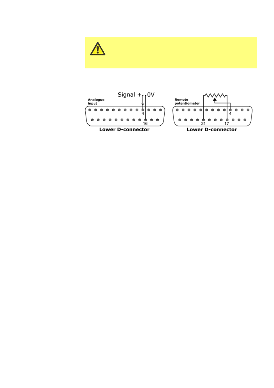
21.1 Speed: analogue input
It is possible to control the speed of the pump remotely by one of these methods:
a voltage analogue signal within the ranges 0-10V or 1-5V; or a current analogue
signal within the range 4-20mA; or a remote potentiometer.
The analogue process signal must be applied to pin 4 of the lower D-connector. 0V
to pin 16. The pump will provide an increasing flow rate for a rising control signal
(non-inverted response) or an increasing flow rate for a falling control signal (invert-
ed response). See 16.2 Analogue in the Setup menu.
4-20mA circuit impedance: 250
Ω.
For voltage modes, a stable, reliable voltage source can be used with a DC voltmeter.
Circuit impedance: 22k
Ω.
Inverting the response is set up in software. Do not invert the polarity of the pins.
A remote potentiometer with a nominal value of between 1k and 2k with a minimum
of 0.25W should be wired as shown. When using a remote potentiometer, do not
apply a voltage or current control input signal at the same time. The speed control
signal will require calibration relative to the minimum and maximum settings of the
potentiometer. This is done in software - see 16.1 Trim in the Setup section.
When using a remote potentiometer, it is important to set the analogue input to volt-
age in the Setup menu. Otherwise the reference voltage supply from pin 21 will be
overloaded and will not provide a full 5V or 10V.