3 speed: analogue input – Watson-Marlow 620U User Manual
Page 60
Watson-Marlow 620UN, 620U, 620SN, 620S User Manual
60
Never apply mains power to the terminals within the
620N module. Apply the correct signals to the
terminals shown below. Limit signals to the maximum
values shown. Do not apply voltage across other
terminals. Permanent damage, not covered by warranty, may
result. The maximum rating on the relay contacts of this pump
is 30V DC; maximum load 30W. Note: Also suitable for low
power: ie, 1mA at 5VDC minimum.
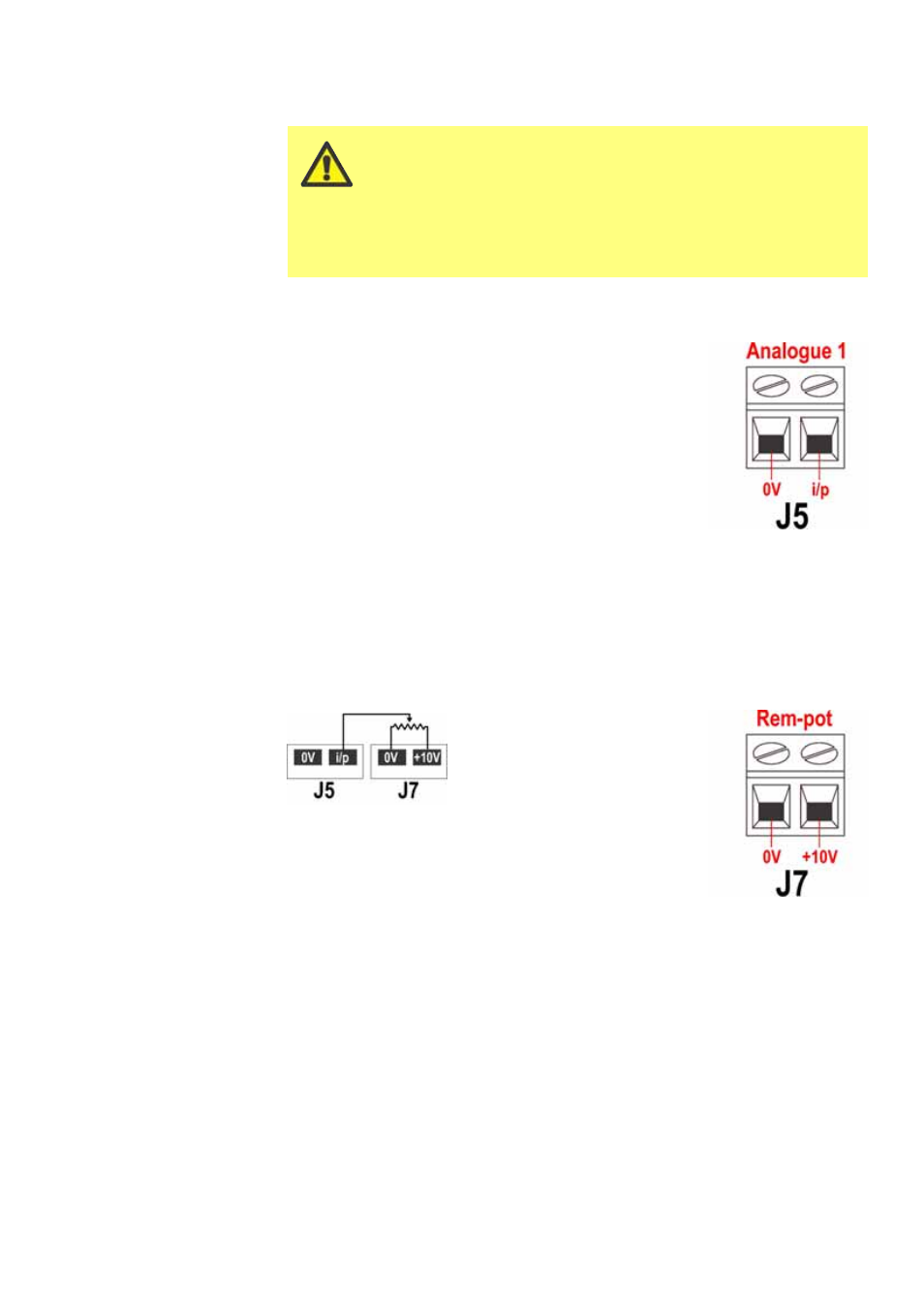
20.3 Speed: analogue input
It is possible to control the speed of the pump remotely by
one of these methods: a voltage analogue signal within the
ranges 0-10V or 1-5V; or a current analogue signal within
the range 4-20mA; or a remote potentiometer using the 10V
supply at J7.
The analogue process signal must be applied to the i/p ter-
minal of the Analogue 1 connector (J5). Ground to the 0V
terminal of the same connector. The pump will provide an
increasing flow rate for a rising control signal (non-inverted
response) or an increasing flow rate for a falling control sig-
nal (inverted response). See 16.2 Analogue in the Setup
menu.
4-20mA circuit impedance: 250
Ω.
For voltage modes, a stable, reliable voltage source can be used with a DC voltmeter.
Circuit impedance: 22k
Ω.
Inverting the response is set up in software. Do not invert the polarity of the termi-
nals.
A remote potentiometer with
anominal value of between 1k and
2k with a minimum of 0.25W
should be wired between the ter-
minals of the Rem-pot connector
(J7) and the i/p terminal of the
Analogue 1 connector (J5). When
using a remote potentiometer, do not apply a voltage or cur-
rent control input signal at the same time. The speed control
signal will require calibration relative to the minimum and
maximum settings of the potentiometer. This is done in soft-
ware. See 16.1 Trim in the Setup section.
When using a remote potentiometer, it is important to set the analogue input to volt-
age in the Setup menu. Otherwise the reference voltage supply from the Rem-pot
connector will be overloaded and will not provide a full 5V or 10V.