1 620n module removal and replacement – Watson-Marlow 620U User Manual
Page 56
Watson-Marlow 620UN, 620U, 620SN, 620S User Manual
56
UN
20 Automatic control wiring
using the 620N module
Interfacing the pump with other devices is by means of screw-terminal connectors
within the 620N watertight module at the rear of the pump. Suitable cable must be
passed into the module through one or more watertight cable glands and connect-
ed appropriately. The module must be removed to allow this.
It is important to check that the pump’s voltage set-
ting matches the supply. The voltage selection switch
is on the rear panel of the drive. The module must be
removed (and replaced) to allow it to be checked.
20.1 620N module removal
and replacement
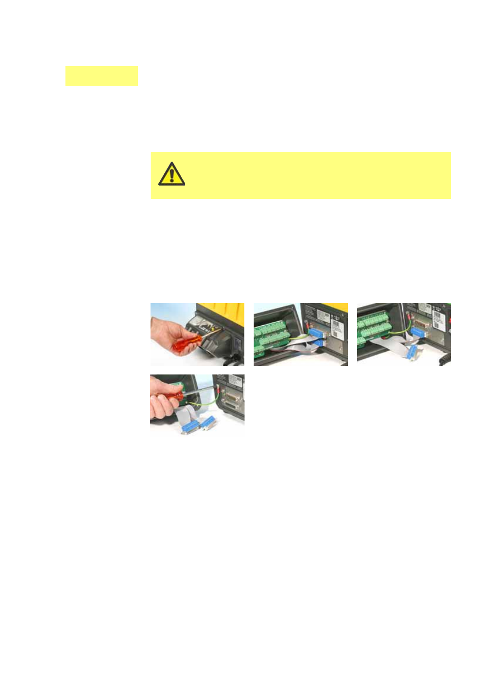
To remove the 620N watertight module:
The module is secured to the back of the drive unit by six M5x12 Pozidriv counter-
sunk stainless steel screws.
Remove the six screws using a suitable crosspoint screwdriver, leaving the top
centre screw till last. Even when all screws have been removed, the sealing
strip may cause the module to adhere to the drive. If so, a gentle tap will free
it. Do not use a tool to lever it off.
The sealing strip should be retained within its channel on the face of the mod-
ule. The transparent on/off switch cover should be retained on its flange on the
face of the module. Check the integrity of the seal and the transparent on/off
switch cover. If either is damaged, it must be renewed to maintain ingress pro-
tection.
If necessary, unplug the two 25-way D-connectors linking the module to the
pump drive. If necessary, remove the module’s earth link from the back of the
drive. However, the link is long enough to allow the module to fold back to give
access to the the circuit board inside and to the back of the drive