9 pump status outputs, 1 logic output 1 – Watson-Marlow 620U User Manual
Page 72
Watson-Marlow 620UN, 620U, 620SN, 620S User Manual
72
21.9 Pump status outputs
Important: pump status outputs
All four outputs can be configured in software to output a range of
parameters: see 16.4 Outputs under Setup.
Outputs 1 and 2 are available simultaneously from the upper and lower
D-connectors. The outputs from the lower D-connector operate at 5V
TTL only.
All four outputs available from the upper D-connector are open-collec-
tor.
By applying a positive voltage to a maximum of 24V to pin 22 of the
upper D-connector, all the outputs from this plug are at that voltage:
pin 22 is commoned with pins 23, 24 and 25. Care must be taken to
ensure that the supply voltage has sufficient capability to drive all the
loads applied to all outputs used. Important: The total load of the
four logic outputs must not exceed 50mA.
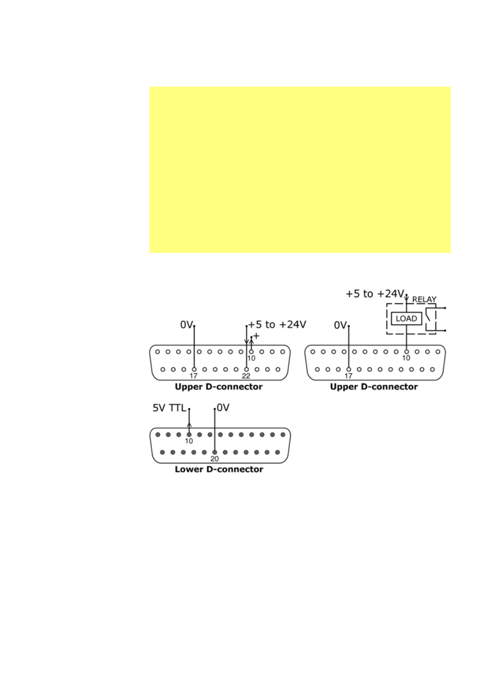
21.9.1 Logic output 1
Output 1 is taken from pin 10 of the upper
D-connector, depending on the logic state
of the function assigned to Output 1.
Alternatively, a load such as a relay coil
may be connected to pin 10, ground to pin
17. Current will flow through the circuit
depending on the logic state of the func-
tion assigned to Output 1. Do not connect to any device requiring more than 50mA.
Additionally, output 1 is available as a 5V TTL logic signal on pin 10 of the lower D-
connector. It will change state corresponding to the logic state of the function
assigned to Output 1. Do not connect to any device requiring more than 1 TTL load.
By default, output 1 is configured to indicate Run/Stop status. See 12 Switching the
pump on for the first time.