ATL Telecom OM100 User Manual
Page 15
The router connection is configured independently, so its transmit clock could either be
looped, or derived from its own internal clock source.
Of course it is not mandatory to use an external reference clock at the PDH interface, so the
above example could be equally configured to use independent timing for all channels. The
choice on whether to use the "lock clock" option, or not depends upon how the rest of the
network has been configured.
ATL USER GUIDE
OM100 Optical Multiplexer
27
26
ATL USER GUIDE
OM100 Optical Multiplexer
Notes:
1. The "lock clock" option is set on a per port basis. Any number of ports may be locked to
the timing reference on port 1, whilst other ports may be timed independently. For example,
ports 1, 2 & 3 may be locked to the timing reference, whilst port 4 remains independent.
2. On the receive side, each "locked" E1 user port derives its own timing from the incoming
E1 signal. This is re-timed to the master reference clock on port 1 before onward transmission.
This permits some flexibility within the terminating equipment. Of course the DTE must be
configured for looped timing, with its transmit clock derived from the timing it receives from
the OM100.
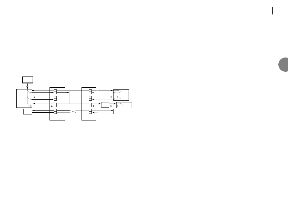
Example network
Notes:
There is no need for a master reference clock on the customer's equipment. However, special
attention must be paid to the clocking scheme used. The customer's equipment must either
be configured for looped timing, or to use a master clock from one of the ports (either is
acceptable). As all "locked" ports use the same clock, a master timing reference can be
derived from any of these ports.
In the above example PABX 1 has each of its two ports configured for looped timing, although
it could have been configured to use a master clock derived from port 1 (or port 2).
PABX 2 has only one user port connection. Again it is configured for looped timing.
The E1 extender can either be configured for looped timing, or operated with independent
timing.
RX
TX
RX
TX
RX
TX
RX
TX
PORT1
PORT2
PORT3
PORT4
Master unit
RX
TX
RX
TX
RX
TX
RX
TX
PORT1
PORT2
PORT3
PORT4
Slave unit
.
.
.
SDH
add
/
drop
mux
Reference
clock
Data
network
PABX
1
PABX
2
Router
E1
extender
Customer’s equipment
Network equipment
OM100
OM100
3