Troubleshooting gre – H3C Technologies H3C S12500 Series Switches User Manual
Page 194
181
Last 300 seconds output rate: 0 bytes/sec, 0 bits/sec, 0 packets/sec
0 packets input, 0 bytes, 0 drops
0 packets output, 0 bytes, 0 drops
# From Switch B, ping the IP address of VLAN-interface 100 on Switch A.
[SwitchB] ping -a 10.1.3.1 10.1.1.1
PING 10.1.1.1 (10.1.1.1) from 10.1.3.1: 56 data bytes
56 bytes from 10.1.1.1: icmp_seq=0 ttl=255 time=11.000 ms
56 bytes from 10.1.1.1: icmp_seq=1 ttl=255 time=1.000 ms
56 bytes from 10.1.1.1: icmp_seq=2 ttl=255 time=0.000 ms
56 bytes from 10.1.1.1: icmp_seq=3 ttl=255 time=0.000 ms
56 bytes from 10.1.1.1: icmp_seq=4 ttl=255 time=0.000 ms
--- 10.1.1.1 ping statistics ---
5 packet(s) transmitted, 5 packet(s) received, 0.0% packet loss
round-trip min/avg/max/stddev = 0.000/2.400/11.000/4.317 ms
The output shows that Switch B can successfully ping Switch A.
163B
Troubleshooting GRE
The key to configuring GRE is to keep the configurations consistent. Most faults can be located by using
the debugging gre or debugging tunnel command. This section analyzes one type of fault for illustration,
with the scenario shown in
816H
Figure 78
.
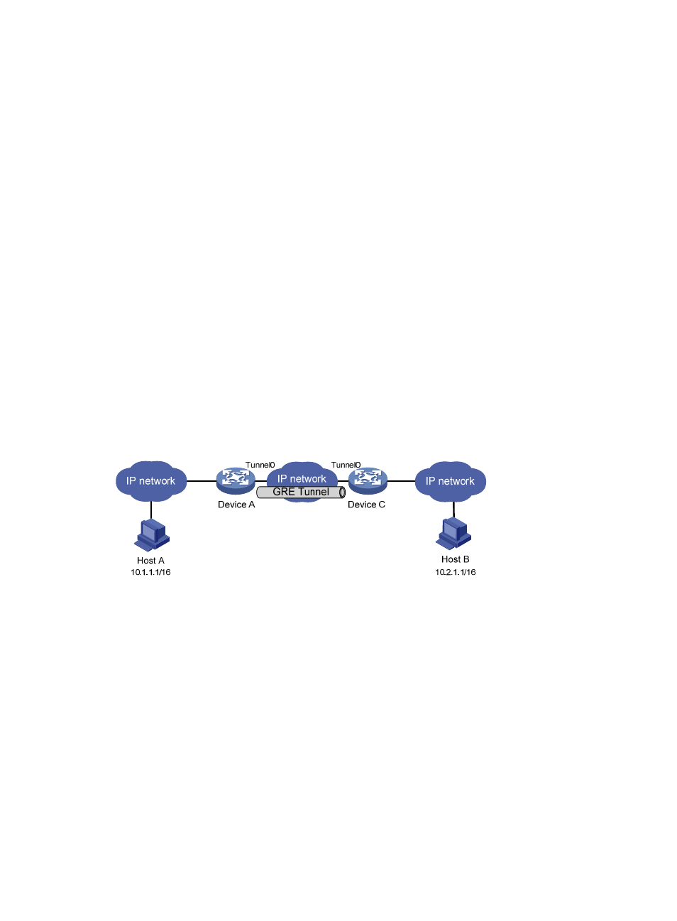
Figure 78 Network diagram
434B
Symptom
The interfaces at both ends of the tunnel are configured correctly and can ping each other, but Host A
and Host B cannot ping each other.
435B
Analysis
It may be because that Device A or Device C has no route to reach the peer network.
436B
Solution
1.
Execute the display ip routing-table command on Device A and Device C to view whether Device
A has a route over tunnel 0 to 10.2.0.0/16 and whether Device C has a route over tunnel 0 to
10.1.0.0/16.
2.
If such a route does not exist, execute the ip route-static command in system view to add the route.
Take Device A as an example:
[DeviceA] ip route-static 10.2.0.0 255.255.0.0 tunnel 0