H3C Technologies H3C S12500 Series Switches User Manual
Page 91
78
As shown in
738H
Figure 35
:
•
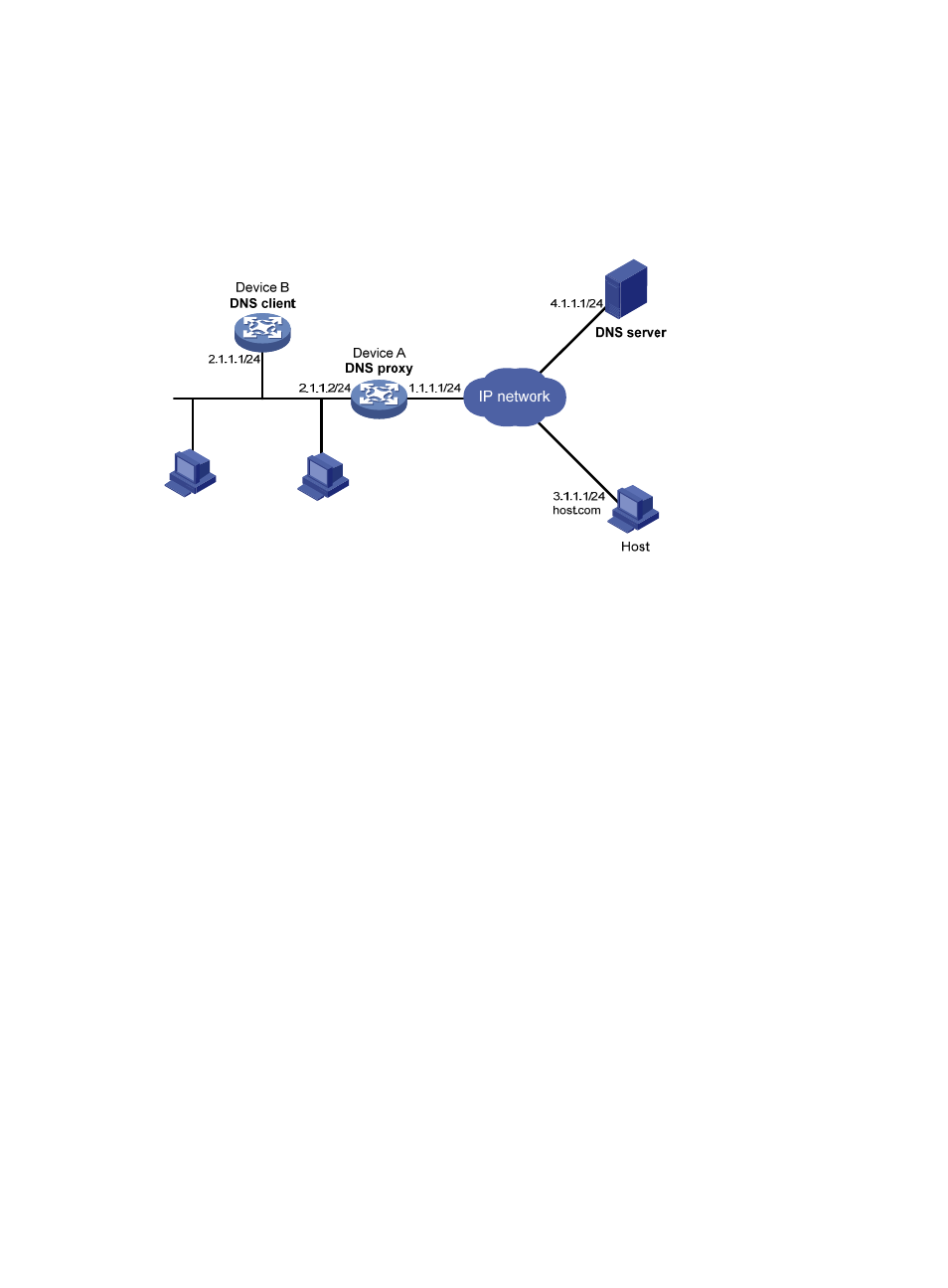
Specify Device A as the DNS server of Device B (the DNS client). Device A acts as a DNS proxy.
The IP address of the real DNS server is 4.1.1.1.
•
Configure the IP address of the DNS proxy on Device B. DNS requests of Device B are forwarded
to the real DNS server through the DNS proxy.
Figure 35 Network diagram
362B
Configuration procedure
Before performing the following configuration, assume that Device A, the DNS server, and the host can
reach each other and the IP addresses of the interfaces are configured as shown in
739H
Figure 35
.
1.
Configure the DNS server:
This configuration may vary with DNS servers. When a PC running Windows Server 2000 acts as
the DNS server, see "
740H
Dynamic domain name resolution configuration example
" for configuration
information.
2.
Configure the DNS proxy:
# Specify the DNS server 4.1.1.1.
<DeviceA> system-view
[DeviceA] dns server 4.1.1.1
# Enable DNS proxy.
[DeviceA] dns proxy enable
3.
Configure the DNS client:
<DeviceB> system-view
# Specify the DNS server 2.1.1.2.
[DeviceB] dns server 2.1.1.2
363B
Verifying the configuration
# Use the ping host.com command on Device B to verify the connection between the device and the host
is normal and that the translated destination IP address is 3.1.1.1.
[DeviceB] ping host.com
PING host.com (3.1.1.1): 56 data bytes
56 bytes from 3.1.1.1: icmp_seq=0 ttl=255 time=1.000 ms
56 bytes from 3.1.1.1: icmp_seq=1 ttl=255 time=1.000 ms