Multiport arp entry configuration example, Network requirements, Configuration procedure – H3C Technologies H3C S12500 Series Switches User Manual
Page 21
8
Type: S-Static D-Dynamic I-Invalid
IP Address MAC Address VLAN ID Interface Aging Type
192.168.1.1 00e0-fc01-0000 10 GigabitEthernet3/0/1 N/A S
31B
Multiport ARP entry configuration example
169B
Network requirements
As shown in
660H
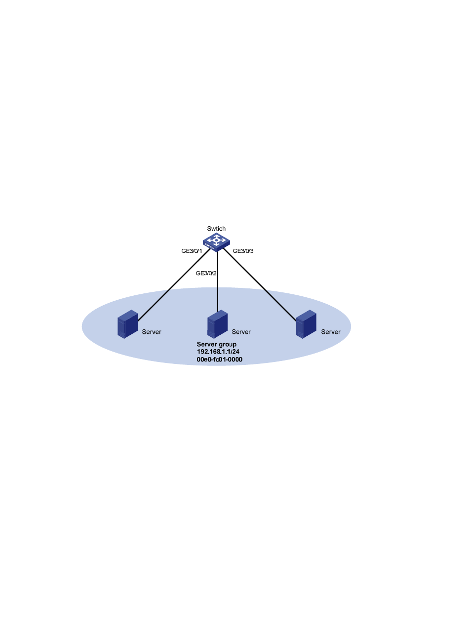
Figure 4
, a switch connects to three servers through interfaces GigabitEthernet 3/0/1,
GigabitEthernet 3/0/2, and GigabitEthernet 3/0/3 in VLAN 10. The servers share the IP address
192.168.1.1/24 and MAC address 00e0-fc01-0000.
Configure a multiport ARP entry to send IP packets with destination IP address 192.168.1.1 to the three
servers.
Figure 4 Network diagram
170B
Configuration procedure
# Create VLAN 10.
<Switch> system-view
[Switch] vlan 10
[Switch-vlan10] quit
# Add GigabitEthernet 3/0/1, GigabitEthernet 3/0/2, and GigabitEthernet 3/0/3 to VLAN 10.
[Switch] interface GigabitEthernet 3/0/1
[Switch-GigabitEthernet3/0/1] port access vlan 10
[Switch-GigabitEthernet3/0/1] quit
[Switch] interface GigabitEthernet 3/0/2
[Switch-GigabitEthernet3/0/2] port access vlan 10
[Switch-GigabitEthernet3/0/2] quit
[Switch] interface GigabitEthernet 3/0/3
[Switch-GigabitEthernet3/0/3] port access vlan 10
[Switch-GigabitEthernet3/0/3] quit
# Create VLAN-interface 10 and specify its IP address.