Common proxy arp configuration example, Network requirements, Configuration procedure – H3C Technologies H3C S12500 Series Switches User Manual
Page 27
14
Task Command
Display common proxy ARP status. display proxy-arp [ interface interface-type interface-number ]
Display local proxy ARP status.
display local-proxy-arp [ interface interface-type interface-number ]
37B
Common proxy ARP configuration example
NOTE:
By default, Ethernet, VLAN, and aggregate interfaces are down. To configure such an interface, bring the
interface up by executing the undo shutdown command.
173B
Network requirements
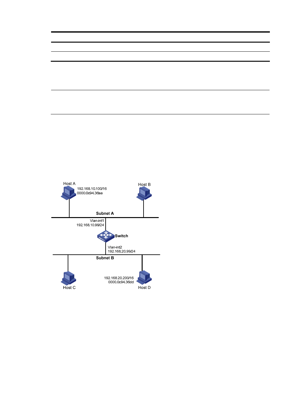
As shown in
661H
Figure 5
, Host A and Host D have the same IP prefix and mask, but they are located on
different subnets separated by the switch (Host A belongs to VLAN 1, and Host D belongs to VLAN 2).
No default gateway is configured on Host A and Host D.
Configure common proxy ARP on the switch to enable communication between the two hosts.
Figure 5 Network diagram
174B
Configuration procedure
# Create VLAN 2.
<Switch> system-view
[Switch] vlan 2
[Switch-vlan2] quit
# Configure the IP address of VLAN-interface 1.
[Switch] interface vlan-interface 1
[Switch-Vlan-interface1] ip address 192.168.10.99 255.255.255.0