Self-defined option configuration example – H3C Technologies H3C S12500 Series Switches User Manual
Page 61
48
[SwitchB-dhcp-class-tt] if-match option 82
[SwitchB-dhcp-class-tt] quit
# Create DHCP address pool aa, specify the address range for the address pool and the address
range for user class tt. Specify gateway and DNS server address.
[SwitchB] dhcp server ip-pool aa
[SwitchB-dhcp-pool-aa] network 10.10.1.0 mask 255.255.255.0
[SwitchB-dhcp-pool-aa] address-range 10.10.1.2 10.10.1.100
[SwitchB-dhcp-pool-aa] class tt range 10.10.1.2 10.10.1.10
[SwitchB-dhcp-pool-aa] gateway-list 10.10.1.255
[SwitchB-dhcp-pool-aa] dns-list 10.10.1.20
339B
Verifying the configuration
After the preceding configuration is complete, clients in a specific user class in subnet 10.10.1.0/24 can
obtain IP addresses and other configuration parameters from the DHCP server (Switch B). Use the display
dhcp server ip-in-use command to view the IP address assigned by the DHCP server.
208B
Self-defined option configuration example
340B
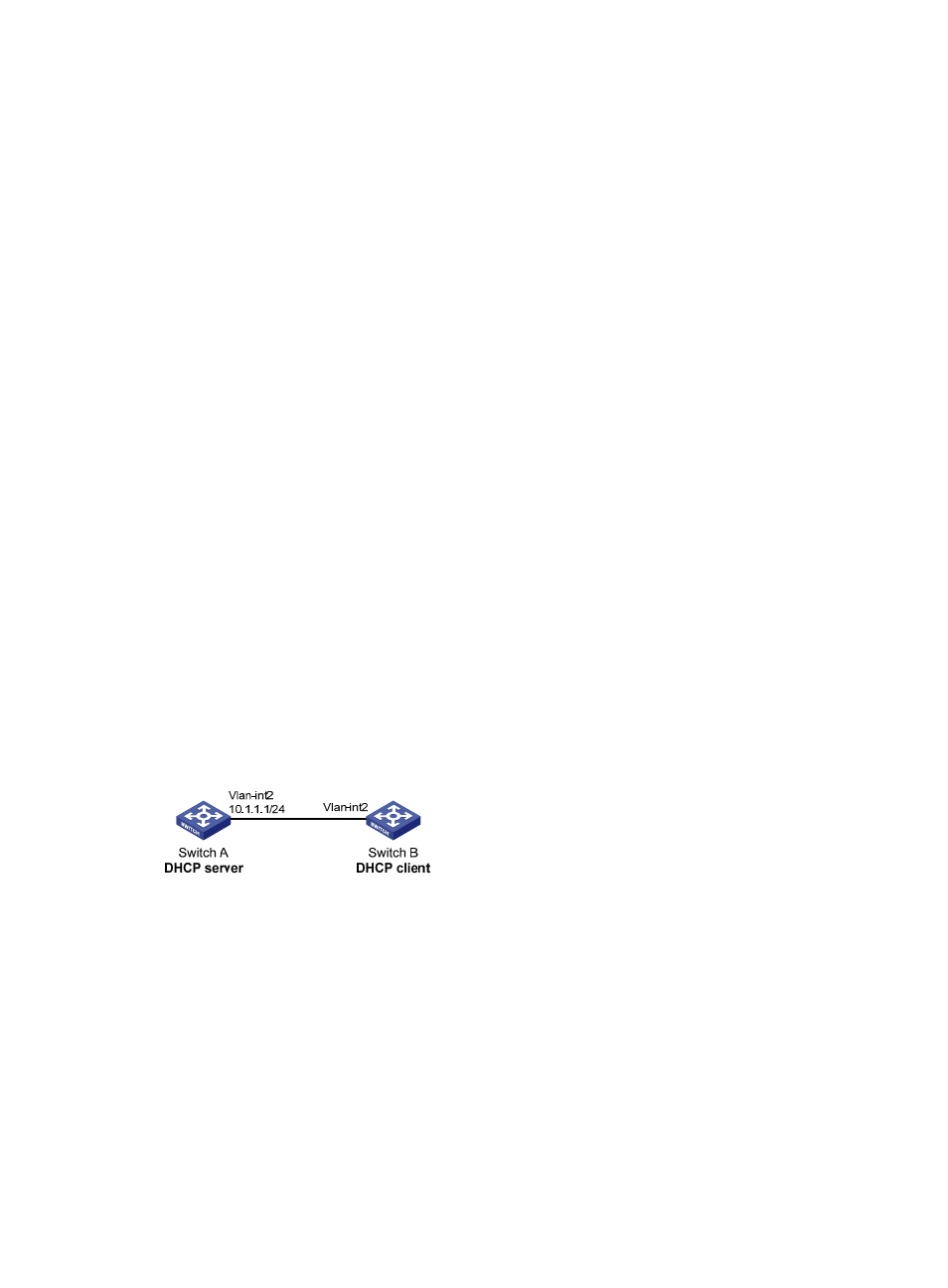
Network requirements
As shown in
694H
Figure 19
, the DHCP client (Switch B) obtains an IP address and PXE server addresses from
the DHCP server (Switch A). The IP address of the DHCP client belongs to subnet 10.1.1.0/24. The PXE
server addresses are 1.2.3.4 and 2.2.2.2.
The DHCP server assigns PXE server addresses to DHCP clients through Option 43, a self-defined option.
The format of Option 43 and that of the PXE server address sub-option are shown in
695H
Figure 13
and
696H
Figure
15
. The value of Option 43 configured on the DHCP server in this example is 80 0B 00 00 02 01 02 03
04 02 02 02 02. The number 80 is the value of the sub-option type. The number 0B is the value of the
sub-option length. The numbers 00 00 are the value of the PXE server type. The number 02 indicates the
number of servers. The numbers 01 02 03 04 02 02 02 02 indicate that the PXE server addresses are
1.2.3.4 and 2.2.2.2.
Figure 19 Network diagram
341B
Configuration procedure
1.
Specify IP addresses for the interfaces. (Details not shown.)
2.
Configure the DHCP server:
# Enable DHCP.
<SwitchA> system-view
[SwitchA] dhcp enable
# Enable the DHCP server on VLAN-interface 2.
[SwitchA] interface vlan-interface 2
[SwitchA-Vlan-interface2] dhcp select server
[SwitchA-Vlan-interface2] quit
# Configure DHCP address pool 0.