Configuration procedure – H3C Technologies H3C WX3000E Series Wireless Switches User Manual
Page 89
80
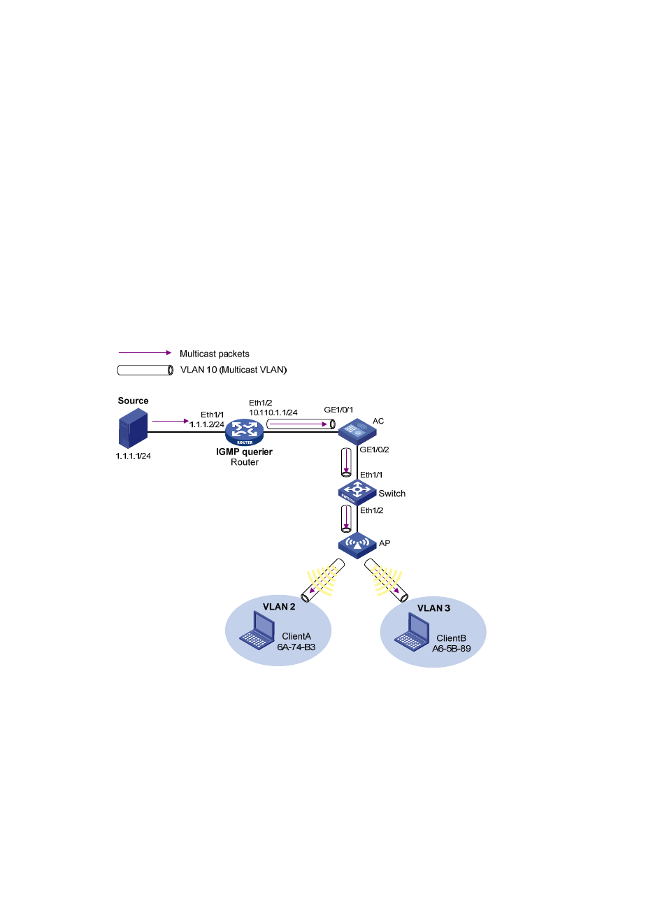
GigabitEthernet 1/0/2. Switch connects to AC through Ethernet 1/1 and to AP through Ethernet 1/2.
IGMPv2 is running between Router and AC. IGMPv2 snooping is running on AC. Router acts as the
IGMP querier.
Create VLAN 10 on AC, assign GigabitEthernet 1/0/1 to VLAN 10, and enable IGMP snooping in the
VLAN. Create WLAN-ESS 1 on AC and configure it as a hybrid port with VLAN 10 as the default VLAN.
Configure the port to allow packets from VLAN 2, VLAN 3, and VLAN 10 to pass. Configure the
MAC-based VLAN feature so that Client A and Client B belong to VLAN 2 and VLAN 3 respectively.
Create VLAN 2, VLAN 3, and VLAN 10 on Switch, and enable IGMP snooping in these VLANs.
Configure Ethernet 1/1 and Ethernet 1/3 as trunk ports, and configure them to allow packets of VLAN
2, VLAN 3, and VLAN 10 to pass.
The multicast source sends multicast data to multicast group 224.1.1.1. Client A and Client B belong to
VLAN 2 and VLAN 3 respectively and they are receivers of the multicast group.
Configure the port-based multicast VLAN feature so that Router just sends multicast data to AC through
the multicast VLAN and AC forwards the multicast data to the receivers that belong to different user
VLANs.
Figure 19 Network diagram
Configuration procedure
1.
Configure the IP address and subnet mask for each interface as per
. (Details not shown.)
2.
On Router, enable IP multicast routing, enable PIM-DM on each interface, and enable IGMP on the
host-side interface Ethernet 1/2.
<Router> system-view
[Router] multicast routing-enable
[Router] interface ethernet 1/1
[Router-Ethernet1/1] pim dm