Configuration procedure – H3C Technologies H3C SecPath F1000-E User Manual
Page 82
21
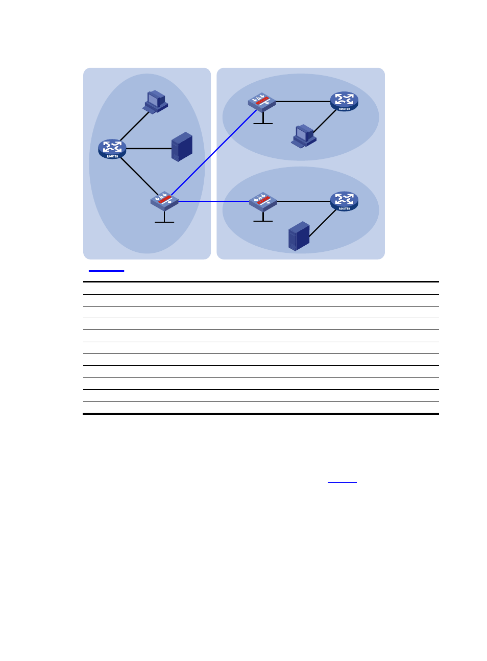
Figure 6 Network diagram for inter-AS multicast configuration leveraging static RPF peers
GE3/0
G
E2
/0
Device B
Device A
Source 1
AS 100
PIM-SM 1
PIM-SM 3
PIM-SM 2
Loop0
Device C
Device D
Device E
Device F
Source 2
GE1/2
GE1/1
GE3/0
GE1/1
GE1/1
Loop0
Receiver
Receiver
Loop0
Static RPF peers
G
E1
/1
G
E1
/3
GE1/1
GE1/1
GE1/2
GE1/2
AS 200
GE2/0
Device
Interface
IP address
Device
Interface
IP address
Device A
GE1/1
10.110.1.2/24
Device D
GE1/1
10.110.4.2/24
GE1/2
10.110.2.1/24
GE1/2
10.110.5.1/24
GE1/3
10.110.3.1/24
Device
E
GE1/1
10.110.6.1/24
Device
B GE1/1 10.110.1.1/24
GE2/0 192.168.3.2/24
GE3/0
192.168.1.1/24
Loop0
3.3.3.3/32
GE2/0
192.168.3.1/24
Device
F
GE1/1
10.110.6.2/24
Loop0
1.1.1.1/32
GE1/2
10.110.7.1/24
Device C
GE3/0
192.168.1.2/24
Source 1
—
10.110.2.100/24
GE1/1
10.110.4.1/24
Source
2
—
10.110.5.100/24
Loop0
2.2.2.2/32
Configuration procedure
Step1
Configure IP addresses and unicast routing
Configure the IP address and subnet mask for each interface as per
. Detailed configuration
steps are omitted.
Configure OSPF for interconnection between the devices in each AS. Ensure the network-layer
interoperation in each AS, and ensure the dynamic update of routing information through a unicast
routing protocol among the devices. Detailed configuration steps are omitted.
Step2
Enable IP multicast routing, enable PIM-SM and IGMP, and configure a PIM-SM domain border
# Enable IP multicast routing on Device A, enable PIM-SM on each interface, and enable IGMP on the
host-side interface GigabitEthernet 1/3.
<DeviceA> system-view
[DeviceA] multicast routing-enable