Setup and operation chapter 2 – Remote Processing RPC-2350 User Manual
Page 10
SETUP AND OPERATION
CHAPTER 2
2-4
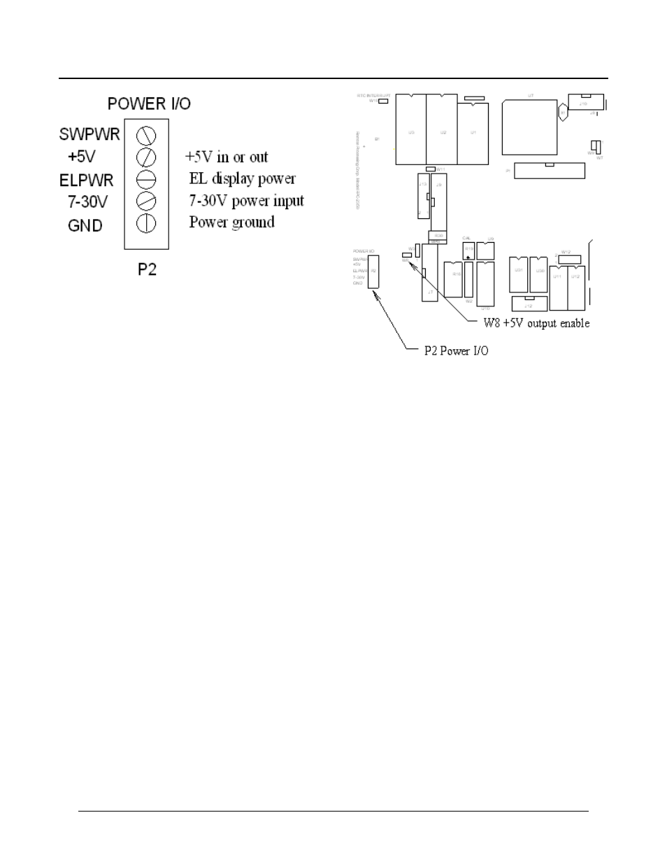
Figure 2-2 Pow er connector detail
Figure 2-3 Pow er and jumper location detail
G r o un d is c on n ec t ed to “ G N D ”
“+ 5V” can be pow er input or output. When W 8 is
installed on the RPC-2350G, it is power output. When
W8 is not installed, it is power input. See Chapter 16 for
more inform ation.
“SWP WR” is a high current switch to ground. See
Chapter 6, High current output at P2 for more
information.
2.
Connect one end of the VTC -9 connector to the 10
pin COM 1 (programm ing) port on the RPC-2350.
Refer to Figure 2-1 for conne ctor location.
Connect the VTC-9 serial cable to the PC' s COM1
or C OM 2 port .
3.
Start your terminal progr am (if not running
already).
4.
Turn on your pow er supply. On pow er up a
copyright message is printed.
CAMBASIC (tm) V1.4
(c)1985-94 Octagon Systems Corporation
(c)1999 Remote Processing Corporation
All rights reserved - free 32434
If a nonsense message appears, your terminal or PC
may not be set to the appropriate communication
parameters. If the system still does not respond,
refer to "T ROU BLESH OOT ING" later in this
chapter.
4.
The system is now in the " imme diate mod e" and is
ready for you to start program ming. T ype the
following program (in upper or lower case:
10 FOR X = 0 TO 2
20 PRINT "
Hello ";
30 NEXT
40 PRINT
Now type RUN
The system will display:
Hello Hello Hello