Chapter 14 multi-mode counter – Remote Processing RPC-2350 User Manual
Page 58
CHAPTER 14
MULTI-MODE COUNTER
14-3
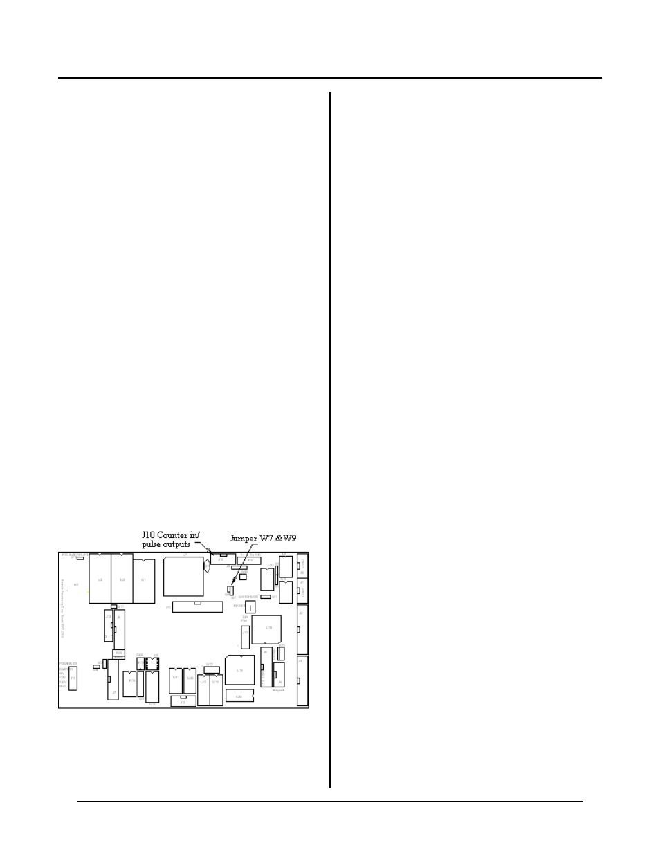
Figure 14-1 Counter and jumper location
CHAPTER SYNOPSIS
Brief description of the counter
High voltage input and level sensing adjustment
Use in program
Measu ring pulse w idth
Measure frequency
DESCRIPTION
MUL TI-MO DE C OUN TER CH APTE R 14
The RPC-2350 has a programm able high speed counter
or quad ratur e encoder . T he 24-bit coun ters ar e capable
of up/dow n, binar y, divide-by-n , and qu adrature inpu ts.
Count frequency is DC to 20 MHZ. The type of counter
is an LSI C omputer Systems L S7166. Its data sheet is in
Appendix A a n d o n di sk a s L S 7 16 6 . P D F
C O U N T ( 8) is u se d to r e ad th e co u nt e r. T h e O U T
command is used to write and progr am the chip.
An interrupt, using ON ITR 1, may be detected on a
carry or borrow.
A high voltag e input, such as a signa l from a proxim ity
sensor, may be connec ted to one of the inputs.
Signals connect via J10. All input lines are pulled high
through 10K input resistors. A quadrature encoder may
be connected directly to J10.
A count is incremented when the signal at the ‘A’ input
goes from low to high.
COUNTER INPUTS AND OUTPUTS
The counter chip has four inputs and two o utputs.
Reference is made to the LS7166 counter reg isters.
These registers are in Appendix A at the end of this
manua l.
Two of the inputs, designated as A and B, are counter
inputs. The ICR (input control register) controls the
function of these inputs. Encoders, switches, and other
such device s are con nected to these inputs. These inpu ts
are very high speed. If you are going to use a
mechanical sw itch, it is best to debounce it first or use
the high voltage input described below.
The ‘A’ input (J10-9 or J10-10 through buffer) operates
as up and dow n count input an d a quadr ature inpu t.
The ‘B’ inpu t (J10-8) can a ct as a down count input,
direction c ontrol for input A, or a quad ratur e input.
Another input is LCTR (J10-6). It can load the counter
or output latch. The ICR register controls the function
of this line. If using it to control the output latch, you
must read each register individually and not transfer the
counter to the output latch as is done by COUN T(8).
See CNT R5.BAS.
The ABGT input (J10-4) enables/disables A/B inputs or
resets the counter. The IC R regsiter controls the
function of this line. Nor mally, it does not have to be
accessed.
The two outputs, C Y and BW are counter ca rry and
borrow signals. They are use to generate an interrupt
(INT1) when the counter goes either through 0 or a
p r e se t . T he s e o u tp u ts a re c on tr o ll e d b y th e O C C R
register. Status is read at the OSR register.
Interrupt selection
Jumper W 7 can be used to interrupt the CPU on a
counter carry, borr ow, or external interrupt. Jumper
W7[1-2] to interrupt on a carry (counter overflows). Set
jumper W7[2-3] to interrupt on a borrow (counter
underflow). Leave W7 open if using an external
interrupt. INT1 goe s to J10-2 for externa l interrupts.
See Fig ure 14-2 for W 7 jumper pin out.