Graphic display port chapter 15, Cable pin outs – Remote Processing RPC-2350 User Manual
Page 71
Advertising
GRAPHIC DISPLAY PORT
CHAPTER 15
15-10
CABLE PIN OUTS
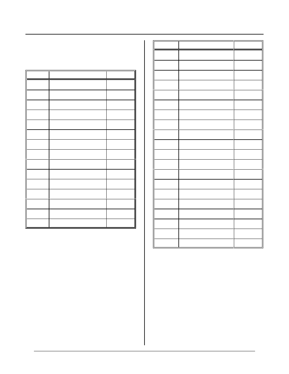
The following tables are cable pin outs for LCD and EL
displays. J9 is the 20 pin display connector on the
board.
J9 Pin #
Description
LCD pin #
1
FLM
1
2
LP
2
3
C P
3
4
W F
4
5
Contrast adjust
5
6
+ 5V
6
7
Ground
7
8
Minus bias (
.
-22V)
8
9
X D 0
9
10
X D 1
10
11
X D 2
11
12
X D 3
12
13
Display on/~off
13
14
no connection
14
15-20
no connection
J13 Pin #
Description
EL pin #
1
Display + 12V
1
2
Display + 12V
2
3
Sef test (no conn ect)
3
4
Reserved
4
5
+ 5V power
5
6
Ground
6
7
FLM/VS
7
8
Ground
8
9
L P / H S
9
10
Ground
10
11
CP/VCLK
11
12
Ground
12
13
X D 0
13
14
Ground
14
15
X D 1
15
16
Ground
16
17
X D 2
17
18
Ground
18
19
X D 3
19
20
Ground
20
Advertising