Multi-mode counter chapter 14 – Remote Processing RPC-2350 User Manual
Page 59
MULTI-MODE COUNTER
CHAPTER 14
14-4
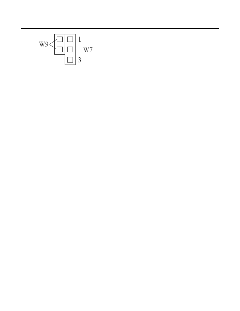
Figure 14-2 W7 and W9 jumper detail
HIGH VOLTAGE INPUT
Connector J10, pin 10 can accept a ±15V signal. As
shipped from the factory, it detects a high input level
(output goes low) at about + 3 volts and a low input
(output goes hig h) at about + 2 volts. This level is
program mable by changing R28.
Lowe r the value of R28 to incr ease the “ high” level.
For exam ple, changing R28 to 23K raises the high input
level thresh old to about 4. 2 volts and the low level to
about 3.2 volts. T he thresholds are approximate and
change fr om lot to lot.
The outpu t of the buffer connects to a c ounter inp ut via
jumper W9. When W9 is jumper ed it will goto the
counter’s “A ” input and to J10-9.
The buff er inver ts the input signal. A count incr ements
when a sign al goes “ high to “ low” on this input.
This line is usef ul for con necting pr oximity sw itches to
the counter. It may be used to filter switch contact
closures by tying a capacitor from its input to ground. A
10K pull-up r esistor is con nected to the inp ut.
PROGRAMMING
The LS7166 is capable of several operating modes, all of
which cannot be discussed. See Appendix A for this
chips operating modes. W hat are shown are exam ple of
how to program this chip and some common operating
modes. .
The counter chip must be initialized before using the
COU NT function. You need to write to the ICR (Input
control register), O CCR (Output control register), and
possibly QR (Quadrature register) in order to set up the
counter. E xamples are given below for different
operating mo des.
The COU NT function returns the current counter value.
S p ec i fi c al ly , C A M B A SI C w r it e s a 2 to th e M C R
(Master Control Register), reads the 3 counter bytes
from the OL (Output latch), and converts it to the proper
internal BA SIC for mat.
The LS7166 has several count related registers. The PR
(Pre set register ) is a kind of holding register . A bit in
the MCR (Master control register) transfer s the
inform ation to the C NTR (counter ). T he PR is u sed to
pre-load the counter . T his pre-loa d value can b e put into
the main counter by setting a bit in the MCR or bringing
the LCTR (J10-6) line low momentarily.
The CN TR is read by first setting another bit in the
MCR to transfer CNT R to OL (Output latch).
CAM BASIC C OUN T(8) function does this.
The counter is capable of generating an interrupt every
time CNT R equal PR, or when CN TR passes through 0
while counting up or down.
NOTE: Pulses from the LS7166 C Y and BW pins m ust
be long enough for the RPC2350 to recognize
an interrupt. C ounting speed is limited to about
100 KHz when interrupts are desired. Even
these can be missed as CAM BASIC shuts off
interr upts at points in the pr ogram , esp ecially
when writing to the graphics screen or F lash.
WARNING:
Do not use the CY or BW pulses to generate an
interrupt in quadrature mode. The pulses are far too
short and are easily missed by hardware. Contact
Remote P rocessing for solutions.
Program Examples
This code, in CN TR1. BAS, r esets the counter and
enables the inp uts. If d esired, connect J2-1 9 to J10-9 to
see the count increment. The count is printed once a
second. If desired, you can bring J10-9 to another
device.
10 pr "Counter test / demo program"
20 pr "Uses J2-19 to generate pulses."
30 pr "Connect to J10-9 (counter
input)"
40 print "Count continues until there
is an error. (about 16 million)
50 pr "Current count is printed every
second."
100 config pio 0,0,1,1,1,0
:'make
port A output
110 out &f1,32 :'reset counter to 0
120 out &f1,72 :'Enable counter A/B