Chapter 6 digital lines – Remote Processing RPC-2350 User Manual
Page 34
CHAPTER 6
DIGITAL LINES
6-1
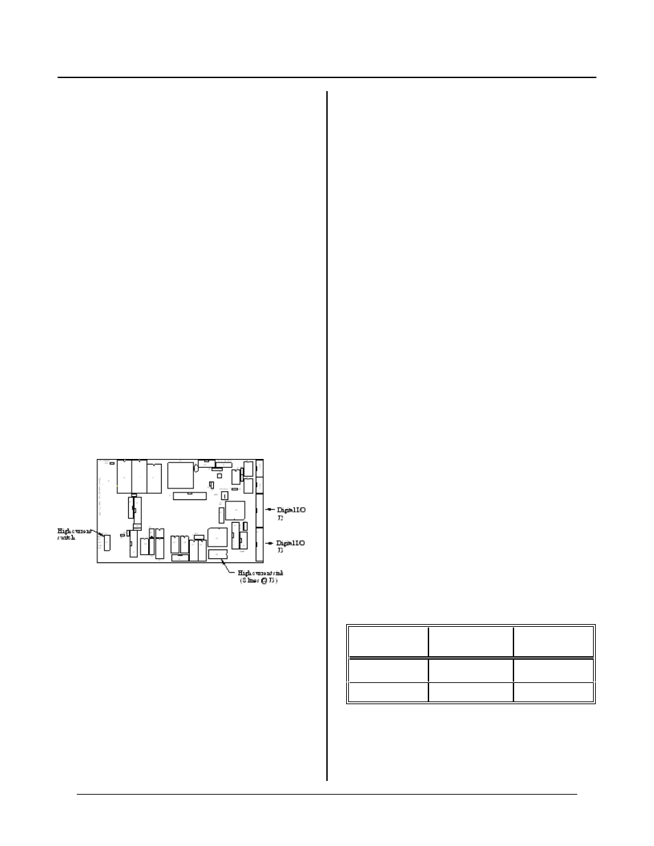
Figure 6-1 Digital I/O connectors
CHAPTER SYNOPSIS
Overview of the digital lines
H o w to p r og r a m
Using high current port
Interfacing to opto racks
DESCRIPTION
DIGITAL LINES CHAPT ER 6
Digital I/ O lines ar e used to inter face with op to-module
racks, switches, low current LED's, and other TTL
devices. The RP C-2350 has 48 of these lines available
through J2 and J3.
J3 is shared with other connectors and functions. Eight
lines are hig h curr ent outputs, capable of sink ing 75 to
200 ma. Another 8 lines on J3 are shared by the keypad
c o nn e ct or , J 5 . St il l a n ot he r 8 li ne s ar e u se d by th e L C D
charac ter por t J6. A table at the end o f this chapter lists
line use at J3.
Eight, 16, or 24 position opto racks are connected to J2
or J3. These opto rac ks accept G4 ser ies opto modules.
G4 series opto modules are used to sense the presence of
AC or D C voltages or switch them. Maximum
switching curr ent is 3 ampere s.
WARNING:
Apply power to the RPC -2350 before applying a
voltage to the digital I/O lines to prevent current
from flowing in and damaging devices. If you
cannot apply power to the RPC-2350 first, contact
technical support for suggestions appropriate to your
application.
A high voltage (±15 volts) input is available at J10-10.
This input is intended for the counter. However, it can
be used as a digital input. Connect jumper block W9-2
to a digital input at J2 or J3.
On power-up or software reset ( or CAMBASIC CALL
0), all digital ports ar e reset to inputs.
DIGITAL I/O PORT
Digital I/O lines on the RPC-2350 are supplied by an
82C55 chip. The chip's lines primarily go to connectors
J2 and J3. Lines to J3 also go to J5 and J6. This part
assumes you will be using all lines at J3 for digital I/O.
The lines on J2 and J3 ar e divided into 3 eig ht bit
groups. P orts A and B can be configured as all inputs or
outputs. Port C can be programm ed as one group of 8
inputs or outputs or as two groups of four lines (upper
and lower C). T he four lines in upper and lower C can
each be progr amme d as all inputs or outputs.
Configuration is done in CAMBA SIC using CON FIG
PIO comm and.
When a line is configured as an output, it can sink a
maximum of 2. 5 mA. at 0.4V and can sourc e over 2.5
mA.at 2.4V. Outputs sink 15 mA.at 1.0V.
J2 and J3 are accessed using CAMBASIC LINE, OPTO,
INP, and OUT statements. LINE r eads or writes to a
port base d on the conne ctor num ber. LINE is genera lly
used with the STB-26 boa rd. OPT O rea ds or w rites to
an opto m odule based o n its position in an M PS opto
rack. INP a nd OU T acces s a byte of data a t a port.
Refer to the tables at the end of this chapter for pin outs,
OPT O, and LINE referen ces.
The base I/O addr ess for J2 is 0 and J3 is 64 when using
INP, OUT, and CON FIG PIO statements. CO NFIG
PIO statement is used to configure the 8255 lines for
inputs and outputs. Upon reset, watchdog time out, or a
CAM BASIC C ALL 0, lines ar e configured for inputs.
J2 and J3 ar e accessed using LIN E or O PTO statements
according to the table below.
Connector
designation
LINE #
terminal
OPTO rack
position
J2
1-25
0-23
J3
101 - 125
100 - 123
LINE #' s access the corresponding pin number on J2 or
J3. L INE # 2 or 102 are not va lid. T his is a + 5 volt
supply.