Display ports chapter 10, Display connector pin out, Commands – Remote Processing RPC-2350 User Manual
Page 53
DISPLAY PORTS
CHAPTER 10
10-2
It is possible to write a LCD character driver in Basic.
This routine will be slow and take up some space.
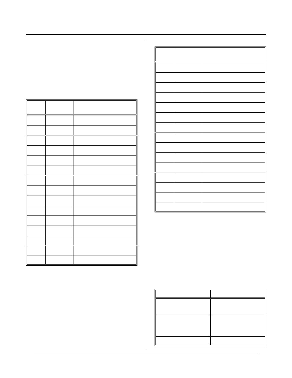
DISPLAY CONNECTOR PIN OUT
The displa y port uses an 82C5 5 for data and contr ol.
The table below lists a pin number and its intended
function. A display may not use all lines even though
they are available.
J6 Pin
82C55
Port/Line
Function WR T display
(LCD d isplays)
1
+ 5V supply
2
Ground
3
A / 4
~RS
4
Contrast Voltage
5
A / 6
E1
6
A / 5
R / ~W
7
No connect
8
No connect
9
No connect
10
A / 7
E2
11
A / 1
DB5
12
A / 0
DB4
13
A / 3
DB7
14
A / 2
DB6
15-20
No connect
The ~ character designates a logical NOT.
LCD char acter displays operate in 4 bit mode. D isplay
lines DB0-DB3 are not connected.
J6 Pin
82C55
Port/Line
Function WR T display
(VF displays)
1
+ 5V supply*
2
Ground*
3
A / 4
D 4
4
No connect
5
A / 6
D 6
6
A / 5
D 5
7
No connect
8
No connect
9
No connect
10
A / 7
Strobe
11
A / 1
D 1
12
A / 0
D 0
13
A / 3
D 3
14
A / 2
D 2
15-20
No connect
VF c haracte r display co nnector table. Displays op erate
in 8 bit mode. Bring bit 7 on display to ground.
Display bit 7 is not used.
*NOTE:
Due to hig h display cur rent dem and, it is
recomm ended that separate + 5 and ground
lines be brought to the display.
COMMANDS
The following is a list of commands used to control the
displays.
Command
Function
CONFIG DISPLAY
Tells system type of
display and initialize s it.
DISPLAY
Cor e comm and to wr ite
to display for printing
and positioning.
CON FIG PIO
Initializes digital port