Power and expansion port chapter 16 – Remote Processing RPC-2350 User Manual
Page 75
POWER AND EXPANSION PORT
CHAPTER 16
16-2
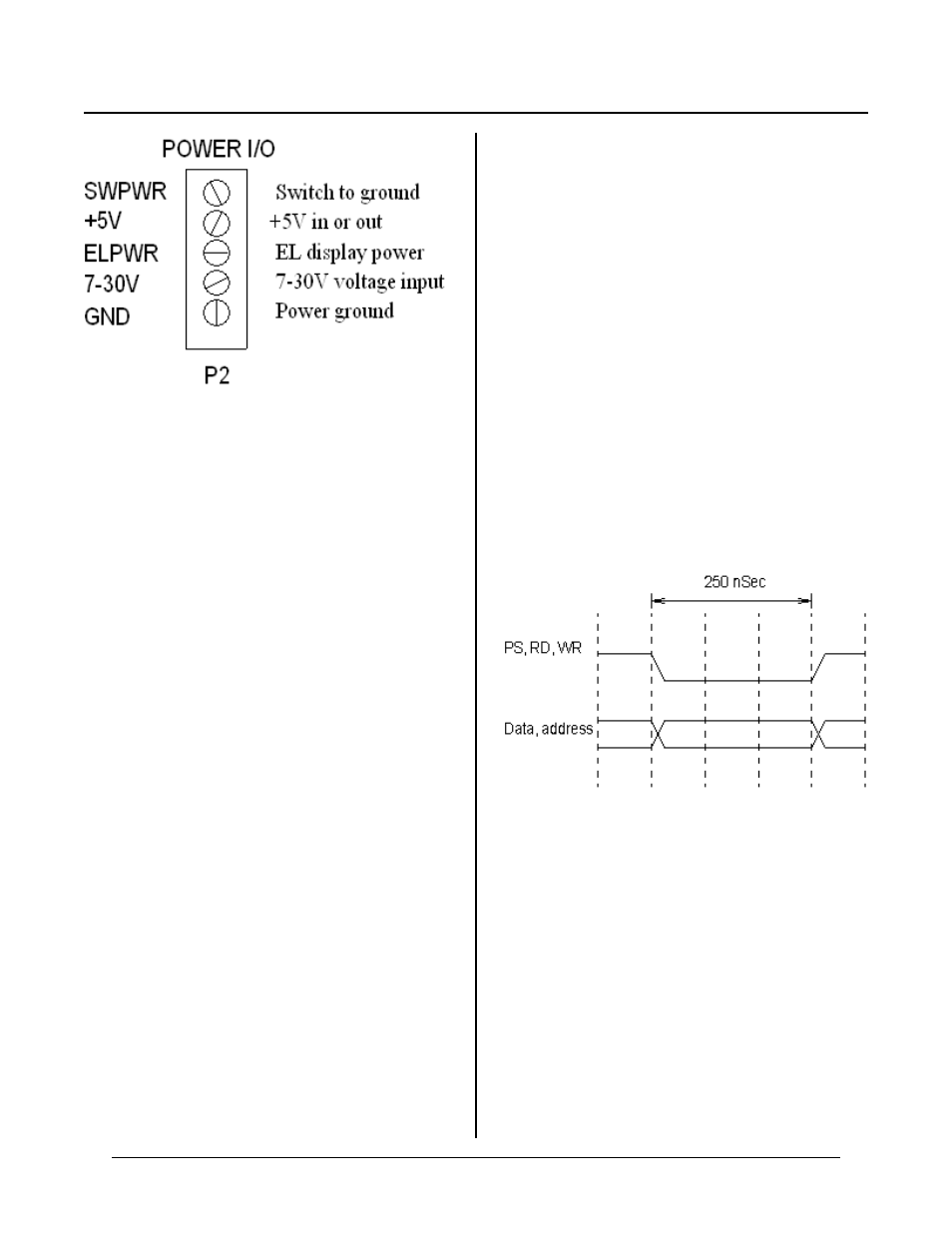
Figure 16-2 Pow er connector detail
POWER OUTPUT
Ther e are sev eral pow er outputs a vailable fr om both
RPC-2350 and RPC-2350G. ±12V power is available at
the analog connector J7. Cur rent is limited to about 40
Ma. See Chapter 8, “AN ALOG POW ER SUP PLY” for
more inform ation.
The RPC -2350G can supply regulated + 5V power at P2,
with 6. 5 to 30V at the input. Appr oximately 750 Ma . is
available for external devices. See "H eat sinking" below
if you intend to draw any significant (> 200 mA.)
current from the board.
This extra cur rent can supply E L displays, opto racks,
LED displays and back lighting, o r other device s.
Heat sinking
A heat sink under U23 is normally not necessary. You
should use a heat sink when all 4 conditions below are
met:
1.
You are supplying 6 to 30VDC to power the
board.
2.
Current from the board (to power external
devices such as opto racks) approaches 750
mA.
3.
The ambient temperatur e will be more than 60°
C .
4.
Supply voltage is usually less than 9 volts.
WARNING:
U23 ca n get VERY HOT, ex ce ed ing 10 0°C (ho tte r
t ha n bo il in g wa t er ) an d st il l o p er a te n or m a ll y. D O
NOT TOUC H U23!
Norm ally U23 is very warm to touch (40°C). As current
deman d increa ses and/ or supply v oltage decr eases, its
tempera ture increase s.
U23 uses a heat sink for a TO-220 IC. Suggested heat
sink by Aav id is: 5772 02B00000. This par t is available
from DigiKey (800 344 4539).
EXPANSION PORT P1
The expansion port brings out address, data, and control
lines for an external board. This external board can
consist of counters, timers, digital I/O, and analog I/O.
6 address and 8 data, read, write, select, and other
power and control lines are provided.
Expansio n port I/ O addr ess range is &100 - & 13F. This
equals 64 addresses.
Timing is simple, based on Z80 I/O signals. Access
times for external devices should be 200 nS. or faster.
Data is read on the rising edge of IRD. See timing
diagram below.
Figure 16-2 I/O timing
A l l l og ic le v el s a r e T T L . H ig h sp e ed C M O S I C ; s
should be used when inter facing to this bus.
Conne ction betwe en P1 an d your bo ard is via a sim ple
26 pin ribbon cable. Limit cable length to 3 inches.