Analog i/o chapter 8 – Remote Processing RPC-2350 User Manual
Page 44
ANALOG I/O
CHAPTER 8
8-2
Initializing Inputs
The RP C-2350 can ha ve up to eight single-ended inputs,
four differential, or a m ixture of single ended and
differential inputs. On a reset, inputs are configured for
0-5V, single ended.
Initialization is performed using the CON FIG AIN
comm and. T he syntax is:
CONFIG AIN channel, input, range
Where:
channel
is from 0 to 7 for single-ended or
differential. Differential inputs require 2 lines and
are spec ially paired as shown b elow. The cha nnels
you specify in a "mixed" application depends upon
what lines ar e used for single ended a nd differe ntial.
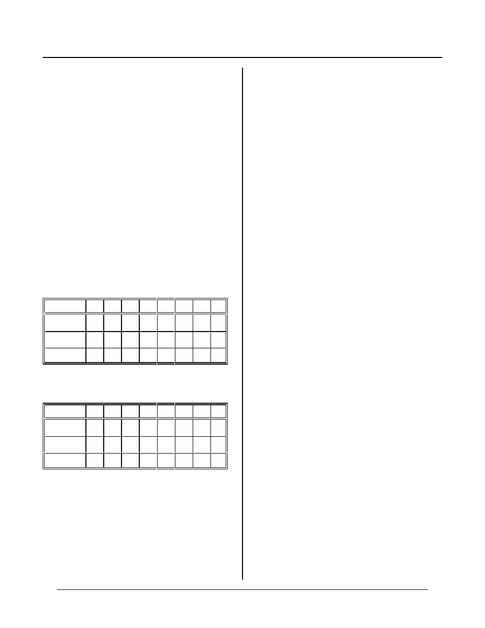
Differential inputs operate in a special way. Use the
following two tables for differ ential inputs.
When channe l = odd
Ch #
0
1
2
3
4
5
6
7
Polar ity
-
+
-
+
-
+
-
+
channel
1
1
3
3
5
5
7
7
J7 pin #
1
3
5
7
9
11
13
15
When channe l = even
Ch #
0
1
2
3
4
5
6
7
Polar ity
+
-
+
-
+
-
+
-
channel
0
0
2
2
4
4
6
6
J7 pin #
1
3
5
7
9
11
13
15
For example , if yo u wanted o ne differ ential input,
channel 0 w ould use J7 pin nu mber s 1 and 3. Single
ended inputs 2-7 are available.
input
specifies single ended or differential. 0 =
differential, 1 = single ended.
range
is voltage input. 0 = ±2.5V and 1 = 0 to
+ 5V.
Differential Mode
When d ifferential m ode is specified , inpu ts are actu ally
pseudo-differential. What this means is that a ground
reference is needed. For example, you cannot place a
battery be tween ch annel 0 and 1 and get an ac curate
reading. T he (-) input must be referenced to ground.
An example of where pseudo-differential works is an
output from a bridge network.
A pseudo-differential input subtracts the DC component
from an input. T he IC maker recomm ends the (-) input
remain stable within 1 count with respect to ground for
best results. Connecting a 0. 1 uF capacitor from the (-)
input to grou nd wor ks well.
When operating in differential mode, r elative + and -
voltages must be connected to specific inputs. When
inputs are reversed, a conversion returns a 0. When the
relative voltage changes, perform a conversion on the
alternate channel. CO NFIG AIN must be perfor med on
both channels to be valid.
Pairs of channels c an be differ ential while oth ers single
ended. Thus, if channel 0 and 1 are differ ential inputs,
channels 2-7 may be single ended.
Examples u sing CON FIG AIN
Below are sample syntaxes for the CON FIG AIN
command:
1. Single ended mode, 0-5V input
CONFIG AIN chan,1,1
The input voltage is from 0 to 5 volts. The result from
the AIN function is 0 for 0.000V and 4095 for
+ 4.9988V. chan may range from 0 to 7, if no other
channels are used for differential inputs.
2. D ifferential mode, 0 to + 5V input
CONFIG AIN chan,0,1
chan c a n b e 0, 2 , 4 , o r 6. T h e in p ut m ay r a ng e fr o m 0
to + 5V. H owever, if the (-) input is more positive than
the (+ ) input, the result w ill always be ze ro. The r esult
from the AIN function is 0 for a difference of 0.000V
and 4095 for a difference of 4.9988V.
3. Single ended, ±2.5V input
CONFIG AIN chan,1,0