Multi-mode counter chapter 14, Commands – Remote Processing RPC-2350 User Manual
Page 61
MULTI-MODE COUNTER
CHAPTER 14
14-6
Signal levels are all TTL logic (0 to 5V).
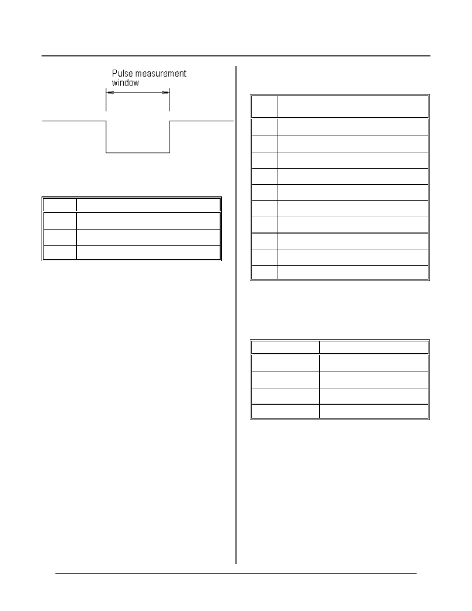
The following signals at J10 ar e used to measur e pulse
widths:
J10 pin
Description
4
Counter gate. Measures when low.
7
4.608 M HZ clock output. Tie to J10-9
9
Clock input. Tie to J10-7
The L S7166 IC R registe r is pro gram med so inp ut A
(J10-9) is up cou nt input and G ATE input (J10-9) ac ts to
enable inputs A/B when low.
If desired, LO AD input (J10-6) can be used to reset the
counter . If this is de sired, make su re the O L reg ister is
program med for 0.
See the demonstration program CNTR6.BAS for a
working example.
Basic operation is a follows:
Set the counter to 0
Read the counter and wait until it stops changing
after it star ts
Read the counter
Multiply result by 2.170139E-7
The result is the actual time.
J10 Pin out
The following is the pin out for J10.
J10
pin
Function
1
Ground
2
4.608 M HZ clock output
3
Sound output
4
Gate input
5
+ 5V
6
Load counter
7
INT 1 input
8
B counter input
9
A counter input
10
High voltage input
COMMANDS
The following commands ar e used with the multi-mode
counter.
Command
Function
COU NT(8)
Reads multi-mode counter
ON ITR 1
Interrupt tasking
I N P
I/O port read
O U T
Write to I/O port