Chapter 10 display port – Remote Processing RPC-2350 User Manual
Page 52
CHAPTER 10
DISPLAY PORT
10-1
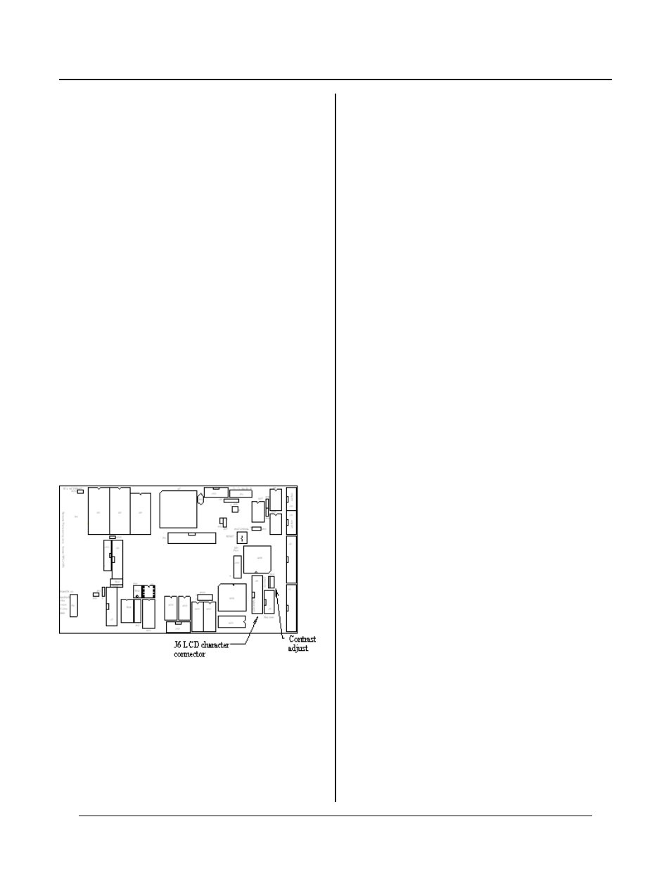
Figure 10-1 LCD character connector and contrast adjust
CHAPTER SYNOPSIS
Differences between RP C-2350 and RPC -2350G
Programm ing for a display
Multiple use note
DESCRIPTION
DISPLA Y POR TS CHA PTER 10
A display, in conjunction with a keypad, can give an
operator feedback on operation status and some level of
control over the p rocess.
There are tw o display ports on the RPC-2350G: J6 is for
LCD char acter displays and J9 or J13 are for graphics
displays. The RPC -2350 has only J6, used for LC D and
VF character displays. This chapter discusses J6. See
Chapte r 15 for graphics display por t.
The L CD charac ter and gr aphic por ts operate
independently of each other. The LCD character port
uses port A fr om an 82C 55 PIO chip. These lines at J6
are shared with some on J3 also. The graphics port has
its own driver and mem ory.
CAM BASIC comm ands are provided to position and
write characters to each display. A dditional commands
are provided to draw lines, turn pixels on and off, and
print large characters on the graphics display.
LCD CHARACTER PORT J6
You can use Liquid Crystal Displays (LC D) or vacuum
f lu o r es c en t d is p la y s a t J 6 . D is p la y si z es r an g e f r om 1
line by 8 character s to 4 lines by 40 character s.
The pin ou t at J6 is designed to plu g directly into Remo te
Processing L CD 4 x 4 0 and LC D 4 x 20 displays.
Simply plug these displays into J6. A contrast
adjustmen t pot, R 13, controls the viewing an gle. This
pot is adjusted after J6 is properly configured.
Any number of other LCD displays may be used. See
the table at the en d of this sub-section for cable pin out.
Configuring J6 for a display
Two lines of CAM BASIC code must be executed in the
proper o rder befo re J6 is ready for displays.
First, you must configure the digital I/O port using the
CONF IG PIO command. Port A must be configured as
an output. If you are using a keypad, then set port C as
shown in the example below. Port B is usually set to an
output to drive the high current sinks. Refer to Chapter
6 , D IG I TA L I/ O, for m ore information on port B and
general program ming information.
P u t t he f ol lo w in g li ne o f c o de in y ou r p ro g r am :
CONFIG PIO 1,0,x,x,x,64
‘X’ parameter is 0 or 1 as needed in your application.
Refer to the CAMBA SIC Programming Manual for more
information about CONFIG PIO. The address for the
display PIO chip is 64.
Next, deter mine the type of display you will be using.
Refer to the CAMBA SIC Programming Manual for a list
of types under CONFIG DISPLAY.
The following example configures J6 for a LC D 4 x 20
display:
CONFIG DISPLAY 64,4,1
The cursor w as selected as blinking.
There are tw o LCD character display demonstration
program s that show how to position and write to the
d is pl ay :
LCD440.BAS
Writes to LCD 4 x 40
LCD420.BAS
Writes to LCD 4 x 20
USING TWO DISPLAYS
The RPC-2350G is not intended to use both character
and graphics displays simultaneously. There is no
provision for switching the software between two
displays.