Analog i/o chapter 8, 20 ma. output – Remote Processing RPC-2350 User Manual
Page 48
ANALOG I/O
CHAPTER 8
8-6
and can be either 0 or 1. channel 0 is on pin 17 and
1 is on pin 19.
value is the value to output from 0 to 4095.
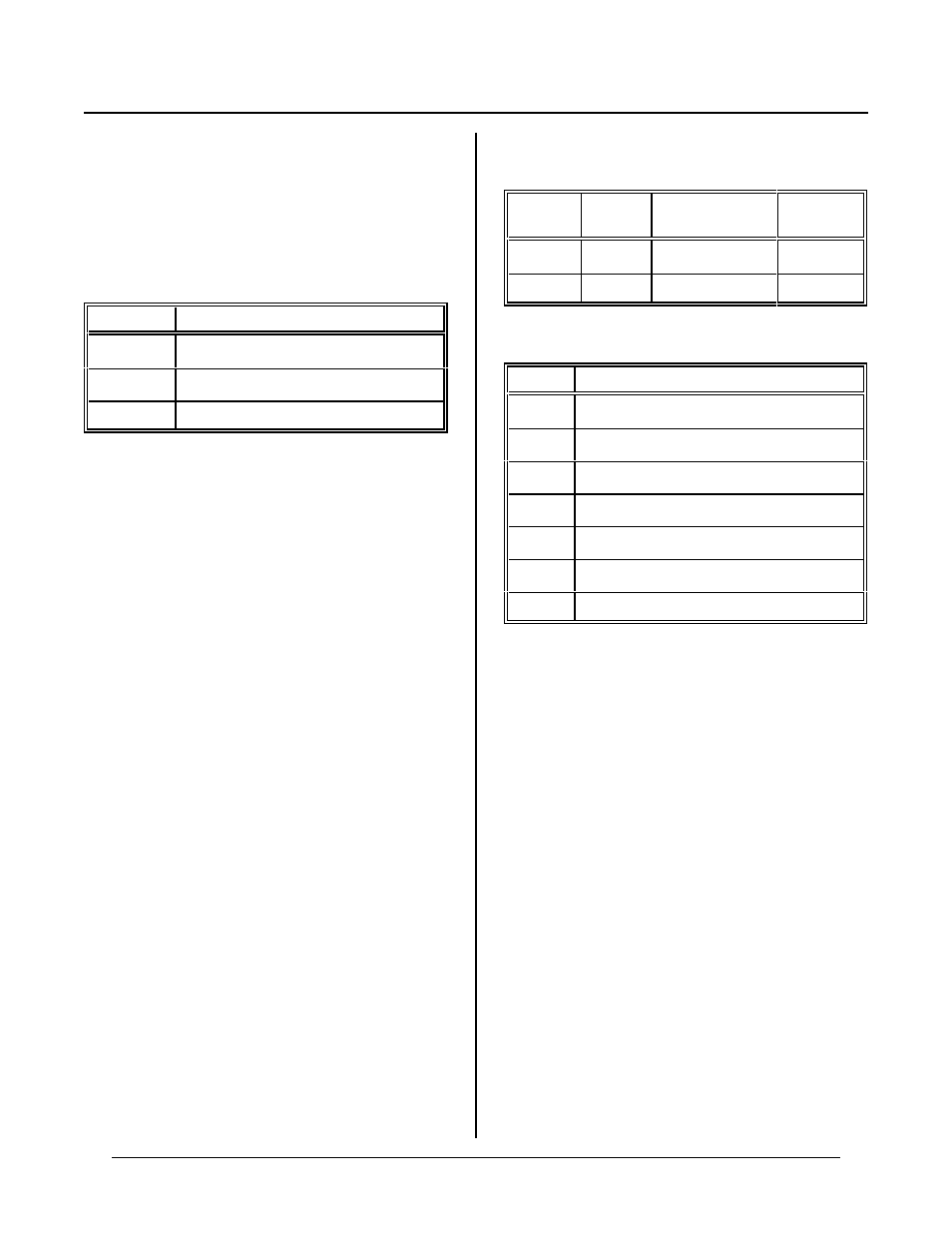
Use the following table to convert from a desired voltage
to a value.
Range
Form ula
0 to 5V
value= V * 819
0 to 10V
value= V * 409.5
-5 to + 5V
value= V * 409.5 + 2047.5
The result of the formula produces a number which can
be used in place of value.
Output Current
D/ A output im pedance is 0. 5 ohms. Short cir cuit
curr ent is 40 mA . T he analog po wer su pply limits this
current to something a little less. Practical maximum
output current from a D/A is 10 mA.
Noise
Analog outputs generate noise in the 100KHz +
freque ncy ran ge. Many devices ar e not affected by this
noise. How ever, if noise is a problem, put a capacitor
(1 µF or so) on the output. Pads are provided at C23
and C24 near J7. C23 filters output 0 and C24 filters
output 1.
4-20 mA. OUTPUT
Two 4-20 mA. outputs are optionally available.
Interface is at J12. Curr ent outputs are driven by the
voltage DAC' s. Configur e each DAC used for 0-10V
output to driv e the curr ent output.
Analog output 1 may be optionally used for software
contrast c ontrol on the LCD graphics display. When it
is used for this purpose, 4-20 mA output may not be
used for th is channel.
When you use a DAC to drive a current output, it cannot
be used for voltage output.
Curr ent output is proportional to the DAC voltage
driving it. To progr am a curre nt, you progr am a voltage
using the AOT comma nd. T hus, 0 V output supplies 4
mA. output while 10V output supplies 20 mA.
The following table lists J12 pin number, DAC , and
curr ent output.
Output
No.
J12 pin
DAC driver
Current
IC
0
2
U11 (AOT 0)
U30
1
10
U12 (AOT 1)
U31
The follow ing table is J12 pin ou t.
Pin No.
Function
1
.
+ 12V, 40 m A. supply from RPC-2350
2
Curr ent loop 0 output
3,5, 6,9
Ground
4
Curr ent loop 0 voltage power input
6
7-30V input from P2
8
Curr ent loop 1 voltage power input
10
Curr ent loop 1 output
Jumper W12 for 0-10V ou tput for eac h channel yo u will
use as current output. See table in Analog Output above
for jumper instructions.
IC Installation
Current output IC’s are installed in U30 and U31. See
Figure 8-5 for location. The notch in the IC designates
the top. Pin 1 is the upper left of the chip. Orient the
board as shown in Figure 8-5 and install the chips in U30
for chan nel 0 and/ or U 31 for ch annel 1, keeping pin 1 to
the upper left.