Technical information, Jumper descriptions – Remote Processing RPC-2350 User Manual
Page 81
TECHNICAL INFORMATION
18-3
JUMPER DESCRIPTIONS
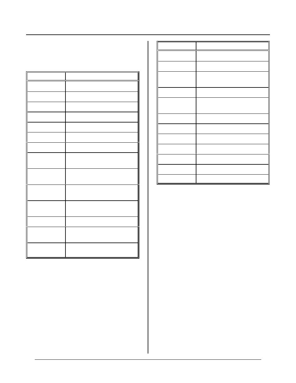
A * after a jumper position indicates factory default and
is jumpered.
Jumper
Description
W1[2-3]*
Watchdog timer 1. 2 Seconds
W1 open
W a t ch d og ti m er 1 5 0 m S
W1[1-2]
Watchdog timer 1. 2 seconds
W2[1-2]*
128K RAM. Flash not affected
W2[4-5]*
128K Flash. RAM not affected
W2[2-3]
512K RAM. Flash not affected
W2[5-6]
512K Flash. RAM not affected
W3[2-3]*
Manual contrast control for
Graphic LCD display
W3[1-2]
Software contrast control for
Graphic LCD display
W4[2-3]*
COM 2 RS-232/485 select at RS-
232
W4[1-2]
COM 2 RS-232/485 select at RS-
485
W5[1-2][3-4]*
RS-485 network terminator.
W6[1-2]*
RS-485 in 2 wire mode (Receive
off when transmitting)
W6[2-3]
RS-485 is 4 wire mode (Receive
always on)
Jumper
Description
W7[1-2]*
INT1 to counter carry
W7[2-3]
INT1 to counter borr ow
W8[1-2]
Regulated + 5V output to board
+ 5V layer.
W9[1-2]
High voltage interface to counter
W10[1-2]
Real time clock inter rupt outpu t to
INT0
W11[1-2]*
Enable a utorun an d graph ics fonts
W12[2-4]*
D/A output 0 to 0-5V
W12[1-3]*
D/A output 1 to 0-5V
W12[8-10]
D/A output 0 to 0-10V
W12[7-9]
D/A output 1 to 0-10V
W12[6-8]
D/A output 0 to ±5V
W12[5-7]
D/A output 1 to ±5V
W13 pr ovides pads for D /A input filter ca pacitors.