Chapter 2 setup and operation, Where to go from here, Troubleshooting – Remote Processing RPC-2350 User Manual
Page 15
CHAPTER 2
SETUP AND OPERATION
2-9
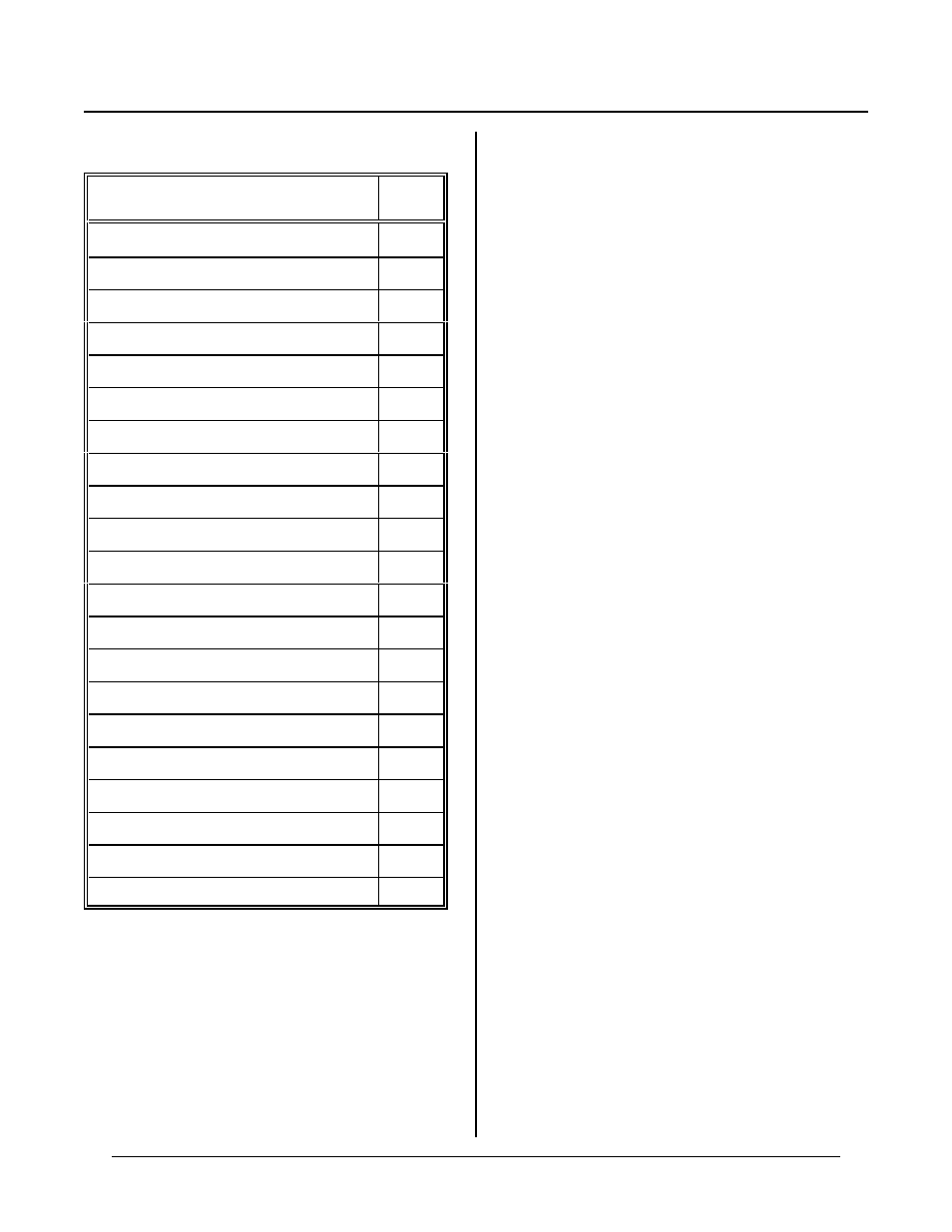
WHERE TO GO FROM HERE
If you w ant to do th is
Go to
chapter
Save a program
3
Autorun a program
3
Know m ore abo ut serial por ts
4
Use the SPI port
4
Using RAM to save variables
5
Storing variables in F lash
5
Configure digital I/O lines
6
Read switch status
6
Use high c urre nt outputs
6
Connect an external opto rack
6
Using calendar/clock
7
Reading vo ltages (Ana log input)
8
Analog output
8
Using a keypad
9
Character display port
10
Sound or timer output
11
Using inter rupts
13
Using high speed counter
14
Graphics display
15
Power input and output
16
Expansion port
16
Also, r efer to the table of contents for a listing of major
functions.
TROUBLESHOOTING
You pr obably tur ned to this section b ecause you could
not get the sign on message. The following are
troubleshooting hints:
1.
Check the power on the RP C-2350 . A good place is
C 1 3 + a n d - . I f i t i s b e lo w 4. 6 5 vo lt s, t h e R P C -
2350 will be r eset. Powe r is 5 ±0. 25 volts. If it
dips intermittently to 4.65 volts (due to switching
noise or ripple), the card w ill reset for about 100
ms. If the noise is frequent enough, the car d will be
in permanent reset. Check U14, pin 6. If it is low
(about 0 volts), then it is in reset. This line shou ld
be high (about + 5 volts).
If you are using a 6-15V supply, make sure it does
not dip below 6V even intermittently. Use a scope
to make sure it does not. A voltmeter m ay not be
good enough.
The same can be said for the 5V supply. Make sure
it does not dip below 4.8V using an oscilloscope.
2.
Check the COM1 port. COM 1 is also known as
console port J1. Rem ove the connector from
COM 1. R efer to the outline dra wing ear lier in this
chapter. Connect an oscilloscope (preferred) or a
voltmeter to pin 3 (Txd ) and gro und. Pin 3 should
be -6 volts or more negative. (Pin 1 is designated
by the ^ sym bol on the conn ector. Pin 3 is next to
it, nearer the key opening.) If you have -6 volts or
more, press the reset switch. If you have a scope
attached, you should see a burst of activity. If you
have a volt m eter, you should see a change in
v o lt a ge . U s in g a F l u ke 8 06 0 A s e t t o m e a su r e AC ,
you should see a mom entary rea ding above 2 volts.
Pre ss reset sev eral tim es to make sure it captu res it.
3.
Install the cable and make sure the voltages and
output activity are still there. Output is from pin 3
on the VT C-9. Check to make su re som ething is
not shorting the output.
4.
Check the serial pa ram eters on y our P C or termin al.
They should be set to:
19200 baud, no parity, 8 data bits, 1 stop
If all of this fails, call technical support listed at the front
of the book.