Chapter 6 digital lines – Remote Processing RPC-2350 User Manual
Page 36
CHAPTER 6
DIGITAL LINES
6-3
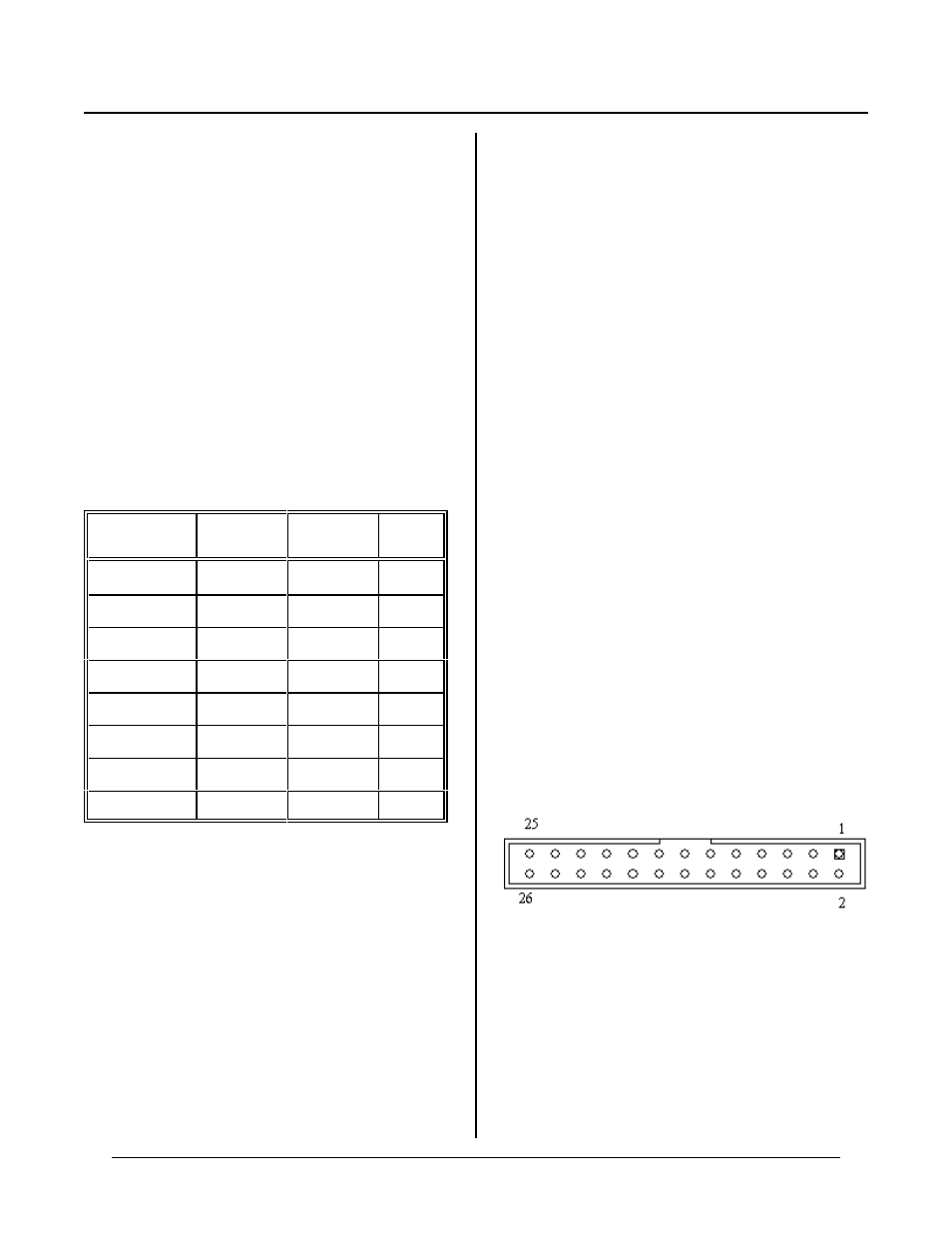
Figure 6-3 IDC pin out viewed from top
lines. The MPS-XX series boards accept OPTO-22 G4
series or Grayhill G5 modules. See Chapter 18,
RESOURCES , for a list of suppliers.
Use the O PTO comm and to acces s and contr ol opto
modules. The LIN E comm and is used to access
individual lines on the STB-26 or MPS-X X rack.
A CM A-26 connects J2 and J3 on the RPC-2350 to the
MPS-XX board. Cable length should be less than 2 feet
for the 8 position rack and 18 inches for the 16 and 24
positions. Excessive cable lengths cause a high voltage
drop an d conseque ntly unreliab le opera tion. Be su re to
supply + 5V and ground to the appropriately marked
terminals.
You must configure the 8255 ports for outputs before
using them. Use the following table to determine the
corr esponding op to channel for a particula r 82C 55 port:
Opto
channe ls
82C55
port
Connector
Addr.
M 0 -M 3
Lower C
J2
2
M 4 -M 7
Upper C
J2
2
M8-M 15
A
J2
0
M16-M 23
B
J2
1
M100-M 103
Lower C
J3
66
M104-M 107
Upper C
J3
66
M108-M 115
A
J3
64
M116-M 123
B
J3
65
"Opto channel" is the position as marked on the MP S-xx
board. The channel number is preceded by a ' M'
character on the MPS board. W hen connecting J3 to an
opto rack, add 100 to the number on the rack. J3 has a
high current output on port A (channels M8-M 15).
Replace U20 with a shunt jumper to operate norm ally.
To turn on an opto module, an output line must be low.
A mod ule is turned off by wr iting a ' 1' to a channel.
The logic a t J3 port A , w ith the high cur rent outpu ts
installed is just the reverse. A ' 1' at a line causes the
m o d ul e t o t ur n O N .
High cur rent outpu ts at J3 port A are option ally
configurable as TTL I/ O by replacing U20 with a DIP
shunt jumper. This keeps logic com patible with ports B
and C. If opto channels 8-15 are used as inputs, then
U20 must be replaced by a DIP shunt jumper.
Configuring digital I/O lines
Lines are configured during progr am execution using the
CONF IG PIO command. On power up or reset, all lines
are inputs.
When a line is configured as an output, it can sink a
maximum of 2. 5 mA. at 0.4V and can sour ce a minimum
of 2.5 mA .at 2. 4V. W hen driving opto modules, the
outputs sink 15 mA.at 1.0V.
Digital I/ O prog ramm ing exam ple
The follow ing exam ple read s a switch at po rt A, bit 3
(J2-25), reads an opto module at channel 1 and writes an
opto module at channel 5. A LE D is controlled at J2-10
(port B, bit 0).
200 D = BIT(0,3)
:'Get status port A
210 F = OPTO(101) :'Read opto module,
ch. 1
220 OPTO 103,ON
:'write module 3
230 BIT 1,0,0
:'turn on J2-10
240 BIT 1,0,1
:'turn off J2-10
250 A = LINE(103) :'Reads pin 3 at J2
260 LINE 4,1
:’Set line # 4 to 1